


Examples: SYST:ERR?
SYSTEM:ERROR?
Returned Parameters: <error number>,<error string>
Related Commands: None
4.3.4 Status Subsystem
This subsystem programs the power supply status registers. The power supply has three groups
of status registers: Operation, Questionable, and Standard Event. The Operation and
Questionable Condition registers monitor the power supply’s operation and alarm status. The
Standard Event group is programmed with Standard Commands as described in Section 4.5, IEEE
488 Event Processing.
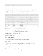
4.3.4.1 Operation Register
This query returns the value of the Operation Register which is a read-only register that holds the
real-time (unlatched) condition of the operational status of the power supply. The bit
configuration of the Operation Register is shown in Table 4.1.
Query Syntax:
STATus:OPERation:CONDition? <>
Examples: STAT:OPER:COND?
STATUS:OPERATION:CONDITION?
Returned Parameters: <NR1> (Register value)
Related Commands: None
Table 4.1
BIT CONFIGURATION OF THE OPERATION REGISTER
BIT
WEIGHT ABBREVIATION
DESCRIPTION
0
1
ARM
Arm
1
2
SS
Soft Start
2
4
LOCK
Locked
3
8
INT
Internal Control
4
16
EXT
External Control
5
32
WTG
Interface is waiting for trigger
6
64
STBY
Standby
7
128
PWR
Power
8
256
CV
Constant Voltage
9
512
RSEN
Remote Sense
10
1024
CC
Constant Current
11
2048
STBY/ALM
Standby or Alarm
55
Summary of Contents for XR III series
Page 1: ...OPERATING AND SERVICE MANUAL XR SERIES III DC POWER SUPPLIES...
Page 2: ......
Page 3: ...MAGNA POWER ELECTRONICS INC 39 ROYAL ROAD FLEMINGTON NJ 08822 February 20 2012...
Page 4: ......
Page 88: ...Figure 4 1 Status Byte Generation Figure 4 2 ESE and ESR Generation 76...
Page 95: ...IEEE Standard CLS ESR ESE STB SRE IDN SAV RCL RST Notes 1 C command Q query 83...
Page 97: ...Figure 5 1 Configuration setup Figure 5 2 GPIB communications setup 85...
Page 99: ...Figure 5 4 Virtual Control Panel Figure 5 5 Command Panel 87...
Page 102: ...Figure 5 7 Calibration Panel Figure 5 8 Firmware Panel 90...
Page 103: ...Figure 5 9 Modulation Panel 91...
Page 123: ...Figure B 1 Information Panel Figure B 2 Configure Panel 111...
Page 124: ...Figure B 3 Reboot in Progress Panel Figure B 4 Web Control Panel 112...


