


up/down keys cause number changes to increase or decreases at a faster rate. Upon nearing the
desired set point number, release and press again to slow down the rate of change.
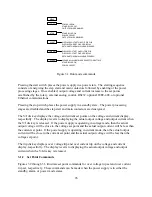
Pressing and holding the clear key for 5 seconds while programming set point commands sets the
OVT and OCT to default values.
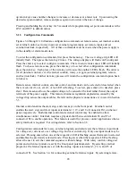
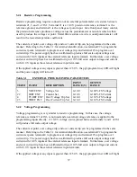
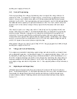
3.1.3 Configuration Commands
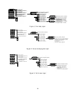
Figures 3.4 through 3.10 illustrate configuration commands set remote sense, set internal control,
set external control, set rotary input, set external program input, set remote input, and set
external interlock, respectively. All of these commands must be made when the power supply is
in the standby or alarm mode state.
To enter the configuration commands, first press the menu key. The over voltage trip LED will
initially flash. Then press the item key 2 times. The voltage display will flash conF (configure).
Press the enter key to select configure commands. The rem sen (remote sense) LED will initially
flash. To choose remote sense, press the enter key or to select other configuration commands,
press the item key. Each press of the item key will cause the another LED to flash. The order is
int ctl (internal control), ext ctl (external control), rotary, ext pgm (external program), remote,
and loc (interlock). Further item key presses will return the configuration command option back
to rem sen.
Remote sense, internal control, external control, and interlock can be selected or deselected when
the rem sen, int ctl, ext, ext ctl, or loc LED is flashing. To select, press enter or to deselect, press
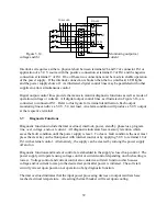
clear. Remote sense allows the output voltage to be sensed at the load rather than at the output
terminals of the power supply. This feature eliminates regulation degradation caused by the
voltage drop across the output cables. Details on the physical connections are covered in Section
3.3.
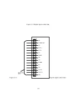
Internal control enables the start, stop, and clear keys on the front panel. External control
enables the start, stop, and clear inputs at terminals 17, 19, and 18 of connector JS1 on the rear
panel, respectively. Both internal control and external control may be enabled to allow
simultaneous control. Interlock requires a physical short between terminals 26 and 37 of
connector JS1 to enable operation. This feature is useful for process control applications when a
safety interlock is required. For wiring details, refer to Section 3.6.
Configuration commands for rotary, external program, and remote sets the reference input mode
for voltage set, current set, over voltage trip, and over current trip. Only one input mode may be
selected. Pressing enter when one of the respective LED is flashing causes that mode to selected
and disables the previously selected mode. Pressing clear when the respective LED is flashing
allows the user to exit the command sequence without change. With rotary control, voltage set
points and current set points are set by the front panel potentiometers. By selecting external
program, all reference inputs are set with the analog inputs at terminals 3, 22, 4, and 23 of
connector JS1. See Section 3.4, for connecting external reference inputs. By selecting remote,
28
Summary of Contents for XR III series
Page 1: ...OPERATING AND SERVICE MANUAL XR SERIES III DC POWER SUPPLIES...
Page 2: ......
Page 3: ...MAGNA POWER ELECTRONICS INC 39 ROYAL ROAD FLEMINGTON NJ 08822 February 20 2012...
Page 4: ......
Page 88: ...Figure 4 1 Status Byte Generation Figure 4 2 ESE and ESR Generation 76...
Page 95: ...IEEE Standard CLS ESR ESE STB SRE IDN SAV RCL RST Notes 1 C command Q query 83...
Page 97: ...Figure 5 1 Configuration setup Figure 5 2 GPIB communications setup 85...
Page 99: ...Figure 5 4 Virtual Control Panel Figure 5 5 Command Panel 87...
Page 102: ...Figure 5 7 Calibration Panel Figure 5 8 Firmware Panel 90...
Page 103: ...Figure 5 9 Modulation Panel 91...
Page 123: ...Figure B 1 Information Panel Figure B 2 Configure Panel 111...
Page 124: ...Figure B 3 Reboot in Progress Panel Figure B 4 Web Control Panel 112...


