


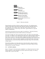

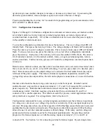


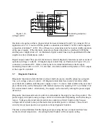
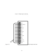

Figure 3.1 Run mode commands
Pressing the start switch places the power supply in a power state. The starting sequence
consists of energizing the step start and main contactors followed by enabling of the power
processing stages. Once enabled, output voltage and current increase to the set points
established by the rotary, external analog control, RS232, optional IEEE-488, or optional
Ethernet communications.
Pressing the stop switch places the power supply in a standby state. The power processing
stages are disabled and the step start and main contactors are denergized.
The V/I dis key displays the voltage and current set points on the voltage and current display,
respectfully. The display reverts to displaying the actual output voltage and output current when
the V/I dis key is released. If the power supply is operating in voltage mode, then the actual
output voltage will be close to the voltage set point and the actual output current will be less than
the current set point. If the power supply is operating in current mode, then the actual output
current will be close to the current set point and the actual output voltage will be less than the
voltage set point.
The trip dis key displays over voltage trip and over current trip on the voltage and current
display, respectfully. The display reverts to displaying the actual output voltage and output
current when the V/I dis key is released.
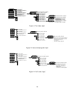
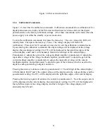
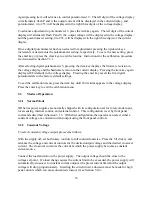
3.1.2 Set Point Commands
Figures 3.2 through 3.3 illustrate set point commands for over voltage trip set and over current
trip set, respectively. These commands can be made when the power supply is in either the
standby, alarm, or power mode states.
MENU
START
STOP
V/I SET
CLEAR
STANDBY LED OFF
POWER LED ON
OUTPUT POWER ENABLED
OUTPUT POWER DISABLED
POWER LED OFF
STANDBY LED ON
CLEARS ALL ALARMS LEDS EXCEPT FOR EXTTRIP
POWER LED OFF
STANDBY LED ON
RETURNS TO NORMAL WHEN RELEASED
DISPLAYS VOLT SET ON VOLT DISPLAY
DISPLAYS CUR SET ON CUR DISPLAY
DISPLAYS OCT SET ON CUR DISPLAY
DISPLAYS OVT SET ON VOLT DISPLAY
RETURNS TO NORMAL WHEN RELEASED
TRIP SET
26
Summary of Contents for XR III series
Page 1: ...OPERATING AND SERVICE MANUAL XR SERIES III DC POWER SUPPLIES...
Page 2: ......
Page 3: ...MAGNA POWER ELECTRONICS INC 39 ROYAL ROAD FLEMINGTON NJ 08822 February 20 2012...
Page 4: ......
Page 88: ...Figure 4 1 Status Byte Generation Figure 4 2 ESE and ESR Generation 76...
Page 95: ...IEEE Standard CLS ESR ESE STB SRE IDN SAV RCL RST Notes 1 C command Q query 83...
Page 97: ...Figure 5 1 Configuration setup Figure 5 2 GPIB communications setup 85...
Page 99: ...Figure 5 4 Virtual Control Panel Figure 5 5 Command Panel 87...
Page 102: ...Figure 5 7 Calibration Panel Figure 5 8 Firmware Panel 90...
Page 103: ...Figure 5 9 Modulation Panel 91...
Page 123: ...Figure B 1 Information Panel Figure B 2 Configure Panel 111...
Page 124: ...Figure B 3 Reboot in Progress Panel Figure B 4 Web Control Panel 112...


