3. SIGNALS AND WIRING
3 - 36
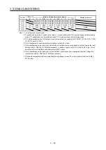
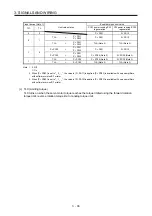
Input device (Note 1)
Limit value status
Enabled torque limit value
TL1 TL
CCW power running/CW
regeneration
CW power running/CCW
regeneration
0
0
Pr. PA11
Pr .PA12
0 1
TLA >
Pr. PA11
Pr. PA12
Pr. PA11
Pr. PA12
TLA <
Pr. PA11
Pr. PA12
TLA (Note 2)
TLA (Note 3)
1 0
Pr. PC35
>
Pr. PA11
Pr. PA12
Pr. PA11
Pr. PA12
Pr. PC35
<
Pr. PA11
Pr. PA12
Pr. PC35 (Note 2)
Pr. PC35 (Note 3)
1 1
TLA
>
Pr. PC35
Pr. PC35 (Note 2)
Pr. PC35 (Note 3)
TLA
<
Pr. PC35
TLA (Note 2)
TLA (Note 3)
Note 1. 0: Off
1: On
2. When [Pr. PD33] is set to "_ 2 _ _", the value in [Pr. PA11] is applied. [Pr. PD33] is available with servo amplifiers
with software version B7 or later.
3. When [Pr. PD33] is set to "_ 1 _ _", the value in [Pr. PA12] is applied. [Pr. PD33] is available with servo amplifiers
with software version B7 or later.
(c) TLC (Limiting torque)
TLC turns on when the servo motor torque reaches the torque limited using the forward rotation
torque limit, reverse rotation torque limit or analog torque limit.
Summary of Contents for MR-JE-_A
Page 9: ...A 8 MEMO ...
Page 15: ...6 MEMO ...
Page 29: ...1 FUNCTIONS AND CONFIGURATION 1 14 MEMO ...
Page 139: ...4 STARTUP 4 38 MEMO ...
Page 187: ...5 PARAMETERS 5 48 MEMO ...
Page 221: ...6 NORMAL GAIN ADJUSTMENT 6 34 MEMO ...
Page 259: ...8 TROUBLESHOOTING 8 8 MEMO ...
Page 265: ...9 DIMENSIONS 9 6 MEMO ...
Page 273: ...10 CHARACTERISTICS 10 8 MEMO ...
Page 339: ...12 COMMUNICATION FUNCTION MITSUBISHI ELECTRIC GENERAL PURPOSE AC SERVO PROTOCOL 12 34 MEMO ...


