6. NORMAL GAIN ADJUSTMENT
6 - 33
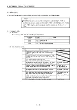
(3) Adjustment procedure of 2 gain adjustment mode
POINT
Set the same value in [Pr. PB07 Model loop gain] for the axis used in 2 gain
adjustment mode.
Step Operation
Description
1
Set to the auto tuning mode.
Select the auto tuning
mode 1.
2
During operation, increase the response level setting value in [Pr.
PA09], and return the setting if vibration occurs.
Adjustment in auto tuning
mode 1
3
Check value of the model loop gain and the load to motor inertia
ratio in advance.
Check the upper setting
limits.
4
Set the 2 gain adjustment mode 1 ([Pr. PA08]: _ _ _ 0).
Select the 2 gain
adjustment mode 1
(interpolation mode).
5
When the load to motor inertia ratio is different from the design
value, select the 2 gain adjustment mode 2 ([Pr. PA08]: _ _ _ 4)
and then set the load to motor inertia ratio manually in [Pr. PB06].
Check the load to motor
inertia ratio.
6
Set the model loop gain of all the axes to be interpolated to the
same value. At that time, adjust to the setting value of the axis,
which has the smallest model loop gain.
Set model loop gain.
7
Considering the interpolation characteristic and motor status,
fine-adjust the model loop gain and response level setting.
Fine adjustment
(4) Parameter adjustment
[Pr. PB07 Model loop gain]
This parameter determines the response level of the position control loop. Increasing the value improves
trackability to a position command, but a too high value will make overshoot liable to occur at settling.
Number of droop pulses is determined by the following expression.
Number of droop pulses [pulse] =
Model loop gain setting
Position command frequency [pulse/s]
Position command frequency =
Speed [r/min]
60
× Encoder resolution (number of pulses per servo motor
revolution)
Summary of Contents for MR-JE-_A
Page 9: ...A 8 MEMO ...
Page 15: ...6 MEMO ...
Page 29: ...1 FUNCTIONS AND CONFIGURATION 1 14 MEMO ...
Page 139: ...4 STARTUP 4 38 MEMO ...
Page 187: ...5 PARAMETERS 5 48 MEMO ...
Page 221: ...6 NORMAL GAIN ADJUSTMENT 6 34 MEMO ...
Page 259: ...8 TROUBLESHOOTING 8 8 MEMO ...
Page 265: ...9 DIMENSIONS 9 6 MEMO ...
Page 273: ...10 CHARACTERISTICS 10 8 MEMO ...
Page 339: ...12 COMMUNICATION FUNCTION MITSUBISHI ELECTRIC GENERAL PURPOSE AC SERVO PROTOCOL 12 34 MEMO ...


