5. PARAMETERS
5 - 43
No./symbol/
name
Setting
digit
Function
Initial
value
[unit]
Control mode
P S T
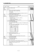
PD25
*DO3
Output device
selection 3
_ _ x x Device selection
Any output device can be assigned to the CN1-24 pin.
Refer to table 5.10 in [Pr. PD24] for settings.
04h
_ x _ _ For manufacturer setting
0h
x _ _ _
0h
PD28
*DO6
Output device
selection 6
_ _ x x Device selection
Any output device can be assigned to the CN1-49 pin.
Refer to table 5.10 in [Pr. PD24] for settings.
02h
_ x _ _ For manufacturer setting
0h
x _ _ _
0h
PD29
*DIF
Input filter
setting
Select a filter for the input signal.
_ _ _ x Input signal filter selection
If external input signal causes chattering due to noise, etc., input filter is used to
suppress it.
0: None
1: 0.888 [ms]
2: 1.777 [ms]
3: 2.666 [ms]
4: 3.555 [ms]
4h
_ _ x _ RES (Reset) dedicated filter selection
0: Disabled
1: Enabled (50 [ms])
0h
_ x _ _ CR (Clear) dedicated filter selection
0: Disabled
1: Enabled (50 [ms])
0h
x _ _ _ For manufacturer setting
0h
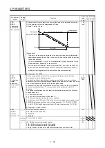
PD30
*DOP1
Function
selection D-1
_ _ _ x Stop method selection for LSP (Forward rotation stroke end) off and LSN (Reverse
rotation stroke end) off
Select a stop method for LSP (Forward rotation stroke end) off and LSN (Reverse
rotation stroke end) off
0: Quick stop
1: Slow stop
0h
_ _ x _ Base circuit status selection for RES (Reset) on
0: Base circuit shut-off
1: No base circuit shut-off
0h
_ x _ _ For manufacturer setting
0h
x _ _ _
0h
PD32
*DOP3
Function
selection D-3
_ _ _ x CR (Clear) selection
Set CR (Clear).
0: Deleting droop pulses at the leading edge of turning on of CR
1: Continuous deleting of droop pulses while CR is on
2: Disabled (Note)
0h
Note. The setting value is available with servo amplifier with software version B7 or
later.
_ _ x _ For manufacturer setting
0h
_ x _ _
0h
x _ _ _
0h
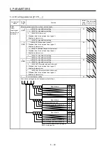
PD33
*DOP4
Function
selection D-4
_ _ _ x For manufacturer setting
0h
_ _ x _
0h
_ x _ _ Rotation direction selection for enabling torque limit
Select a rotation direction which enables the internal torque limit 2 and the external
torque limit.
Refer to section 3.6.1 (5) for details.
0: Enabled in both CCW or positive direction and CW or negative direction
1: Enabled in CCW or positive direction
2: Enabled in CW or negative direction
This digit is available with servo amplifiers with software version B7 or later.
0h
x _ _ _ For manufacturer setting
0h
Summary of Contents for MR-JE-_A
Page 9: ...A 8 MEMO ...
Page 15: ...6 MEMO ...
Page 29: ...1 FUNCTIONS AND CONFIGURATION 1 14 MEMO ...
Page 139: ...4 STARTUP 4 38 MEMO ...
Page 187: ...5 PARAMETERS 5 48 MEMO ...
Page 221: ...6 NORMAL GAIN ADJUSTMENT 6 34 MEMO ...
Page 259: ...8 TROUBLESHOOTING 8 8 MEMO ...
Page 265: ...9 DIMENSIONS 9 6 MEMO ...
Page 273: ...10 CHARACTERISTICS 10 8 MEMO ...
Page 339: ...12 COMMUNICATION FUNCTION MITSUBISHI ELECTRIC GENERAL PURPOSE AC SERVO PROTOCOL 12 34 MEMO ...


