5. PARAMETERS
5 - 13
No./symbol/
name
Setting
digit
Function
Initial
value
[unit]
Control mode
P S T
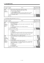
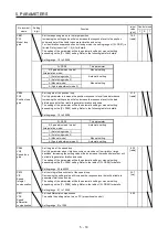
PA13
*PLSS
Command
pulse input
form
_ _ _ x Command input pulse train form selection
0: Forward/reverse rotation pulse train
1: Signed pulse train
2: A-phase/B-phase pulse train (The servo amplifier imports input pulses after
multiplying by four.)
Refer to table 5.3 for settings.
0h
_ _ x _ Pulse train logic selection
0: Positive logic
1: Negative logic
Select the same one as a logic of command pulse train from controller to connect.
Refer to POINT of section 3.6.1 for logic of MELSEC iQ-R series/MELSEC-Q
series/MELSEC-L series/MELSEC-F series.
Refer to table 5.3 for settings.
0h
_ x _ _ Command input pulse train filter selection
Selecting proper filter enables to enhance noise tolerance.
0: Command input pulse train is 4 Mpulses/s or less.
1: Command input pulse train is 1 Mpulse/s or less.
2: Command input pulse train is 500 kpulses/s or less.
3: Command input pulse train is 200 kpulses/s or less.
1 Mpulse/s or lower commands are supported by "1". When inputting commands
over 1 Mpulse/s and 4 Mpulses/s or lower, set "0".
Setting a value not according to the command pulse frequency may cause the
following malfunctions.
Setting a value higher than actual command will lower noise tolerance.
Setting a value lower than actual command will cause a position mismatch.
1h
x _ _ _ For manufacturer setting
0h
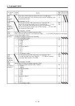
Table 5.3 Command input pulse train form selection
Setting
value
Pulse train form
Forward rotation
command
Reverse rotation
command
_ _ 1 0
Forward rotation
pulse train
Reverse rotation
pulse train
NP
PP
_ _ 1 1
Negati
ve l
ogi
c
Signed pulse train
PP
L
H
NP
_ _ 1 2
A-phase pulse
train
B-phase pulse
train
PP
NP
_ _ 0 0
Forward rotation
pulse train
Reverse rotation
pulse train
NP
PP
_ _ 0 1
P
os
iti
ve l
ogi
c
Signed pulse train
L
H
PP
NP
_ _ 0 2
A-phase pulse
train
B-phase pulse
train
PP
NP
Arrows in the table indicate the timing of importing pulse trains. A-phase pulse train and B-phase pulse train are
imported after they have been multiplied by 4.
Summary of Contents for MR-JE-_A
Page 9: ...A 8 MEMO ...
Page 15: ...6 MEMO ...
Page 29: ...1 FUNCTIONS AND CONFIGURATION 1 14 MEMO ...
Page 139: ...4 STARTUP 4 38 MEMO ...
Page 187: ...5 PARAMETERS 5 48 MEMO ...
Page 221: ...6 NORMAL GAIN ADJUSTMENT 6 34 MEMO ...
Page 259: ...8 TROUBLESHOOTING 8 8 MEMO ...
Page 265: ...9 DIMENSIONS 9 6 MEMO ...
Page 273: ...10 CHARACTERISTICS 10 8 MEMO ...
Page 339: ...12 COMMUNICATION FUNCTION MITSUBISHI ELECTRIC GENERAL PURPOSE AC SERVO PROTOCOL 12 34 MEMO ...


