3. SIGNALS AND WIRING
3 - 9
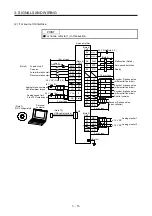
(b) For source I/O interface
POINT
For notes, refer to (1) (a) in this section.
2 m or less
26
MO1
30
LG
29
MO2
± 10 V DC
± 10 V DC
SD
Servo amplifier
(Note 2)
Malfunction (Note 6)
Zero speed detection
47
DOCOM
48
ALM
23
ZSP
24
INP
4
LA
5
LAR
6
LB
7
LBR
34
LG
33
OP
SD
10 m or less
2 m or less
(Note 7)
CN1
LG
DICOM
10 m or less (Note 8)
41
20
46
49
10
11
35
9
3
36
CLEARCOM
12
15
16
14
13
11
CLEAR
RDYCOM
READY
PULSE F+
PULSE F-
PG0
PG0 COM
PULSE R+
PULSE R- 18
10
17
9
DOCOM
CR
RD
PP
PG
NP
NG
LZ
LZR
8
(Note 10)
(Note 13)
(Note 7)
CN1
Positioning module
RD75D
24 V DC (Note 4, 12)
In-position
SD
RA1
RA2
RA3
24 V DC (Note 4, 12)
24 V DC (Note 4, 12)
(Note 1)
2 m or less
10 m or less
42
15
19
43
44
21
27
SD
EM2
SON
RES
LSP
LSN
DICOM
TLA
LG
28
(Note 7)
CN1
+
(Note 9)
MR Configurator2
(Note 7)
CN1
CN3
(Note 11)
Power supply
0 V to +10 V
Encoder A-phase pulse
(differential line driver)
Encoder B-phase pulse
(differential line driver)
Control common
Encoder Z-phase pulse
(open collector)
Control common
Forced stop 2
Servo-on
Reset
Forward rotation
stroke end
Reverse rotation
stroke end
(Note 3, 5)
(Note 5)
Analog torque limit
+10 V/maximum torque
Plate
Plate
Plate
Plate
USB cable (option)
Personal
computer
Analog monitor 1
Analog monitor 2
(Note 15)
(Note 14)
Summary of Contents for MR-JE-_A
Page 9: ...A 8 MEMO ...
Page 15: ...6 MEMO ...
Page 29: ...1 FUNCTIONS AND CONFIGURATION 1 14 MEMO ...
Page 139: ...4 STARTUP 4 38 MEMO ...
Page 187: ...5 PARAMETERS 5 48 MEMO ...
Page 221: ...6 NORMAL GAIN ADJUSTMENT 6 34 MEMO ...
Page 259: ...8 TROUBLESHOOTING 8 8 MEMO ...
Page 265: ...9 DIMENSIONS 9 6 MEMO ...
Page 273: ...10 CHARACTERISTICS 10 8 MEMO ...
Page 339: ...12 COMMUNICATION FUNCTION MITSUBISHI ELECTRIC GENERAL PURPOSE AC SERVO PROTOCOL 12 34 MEMO ...


