


69rlq62d-f714peg4 * Memec (Headquar
ter
s) - Unique
Tec
h,
Insight,
Impact
MAR
VELL CONFIDENTIAL,
UNDER ND
A# 12101050
69rlq62d-f714peg4 * Memec (Headquar
ter
s) - Unique
Tec
h,
Insight,
Impact
MAR
VELL CONFIDENTIAL,
UNDER ND
A# 12101050
69r
lq62d-f714peg4 * Memec (Headquar
ters) - Unique
T
ech, Insight, Impact * UNDER ND
A# 12101050
MAR
VELL CONFIDENTIAL - UNA
UTHORIZED DISTRIB
UTION OR USE STRICTL
Y PR
OHIBITED
PXA300 Processor and PXA310 Processor
Vol. I: System and Timer Configuration Developers Manual
Doc. No. MV-TBD-00 Rev. A
CONFIDENTIAL
Copyright © 12/13/06 Marvell
Page 400
Document Classification: Proprietary Information
December 13, 2006
Not approved by Document Control. For review only.
13.6.2
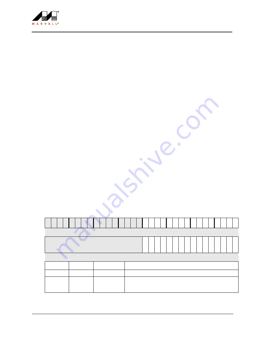
RTC Status Register (RTSR)
The bits within RTSR, defined in
, are categorized as alarm-enable bits, count-enable bits, and
alarm-detect bits.
The alarm-enable bits are used to enable and disable the RTC alarm functions. The RTSR contains the
alarm-enable bits for the timer (ALE), wristwatch (RDALE1 and RDALE2), periodic interrupt (PIALE), and
stopwatch (SWALE1 and SWALE2). The RTSR also contains a 1-Hz clock edge-detection-enable bit (HZE).
The count-enable bits are used to enable and disable the RTC counter functions. The RTSR contains two
count-enable bits: one for the stopwatch (SWCE) and one for the periodic interrupt (PICE). The counters
increment only if their corresponding count-enable bits are set.
The alarm-detect bits indicate whether the corresponding alarm has occurred. The alarm-detect bits are set by the
RTC controller logic if the corresponding enable bits are set and the alarm conditions have been met. The
alarm-detect bits in this register are routed to the interrupt controller where they can be enabled to cause a
second-level interrupt. The alarm-detect bits are reset by writing 0b1 to the bit(s) to be cleared.
When the PXA300 processor or PXA310 processor is in a low-power mode, the alarm-detect bit in the RTSR is
updated if an RTC alarm is detected and the corresponding alarm-enable bit in the RTSR is set.
The RTSR contains alarm-detect bits in the RTSR for the timer (Al), wristwatch (RDAL1 and RDAL2),
stopwatch (SWAL1 and SWAL2), periodic interrupt (PIAL), and the 1-Hz clock edge-detect (HZ).
Note:
Before enabling any of the RTC alarms, the corresponding alarm registers must be written with
valid values. Not doing so will result in spurious wakeups from these alarm sources. For
example, SWAR1/2 must be programmed before enabling SWALE1. Also the inactive alarm
must be programmed to a value much higher than the active alarm to prevent spurious wakeups.
This is a read/write register. Ignore reads from reserved bits. Write 0b0 to reserved bits.
Table 13-6. RTSR Bit Definitions (Sheet 1 of 3)
Physical Address
0x4090_0008 RTSR
RTC Controller
User
Settings
Bit
31 30 29 28 27 26 25 24 23 22 21 20 19 18 17 16 15 14 13 12 11 10 9
8
7
6
5
4
3
2
1
0
reserved
PI
C
E
PI
A
L
E
PI
A
L
SWC
E
SW
A
L
E
2
SW
A
L
2
SW
A
L
E
1
SW
A
L
1
RDALE
2
RDA
L
2
RDALE
1
RDA
L
1
HZ
E
AL
E
HZ
AL
Reset
?
?
?
?
?
?
?
?
?
?
?
?
?
?
?
?
0
0
0
0
0
0
0
0
0
0
0
0
0
0
0
0
Bits
Access
Name
Description
31:16
—
—
reserved
15
R/W
PICE
Periodic Interrupt Count Enable for RTCPICR count register:
0 – RTCPICR counter incrementing is disabled.
1 – RTCPICR counter incrementing is enabled.


