


322
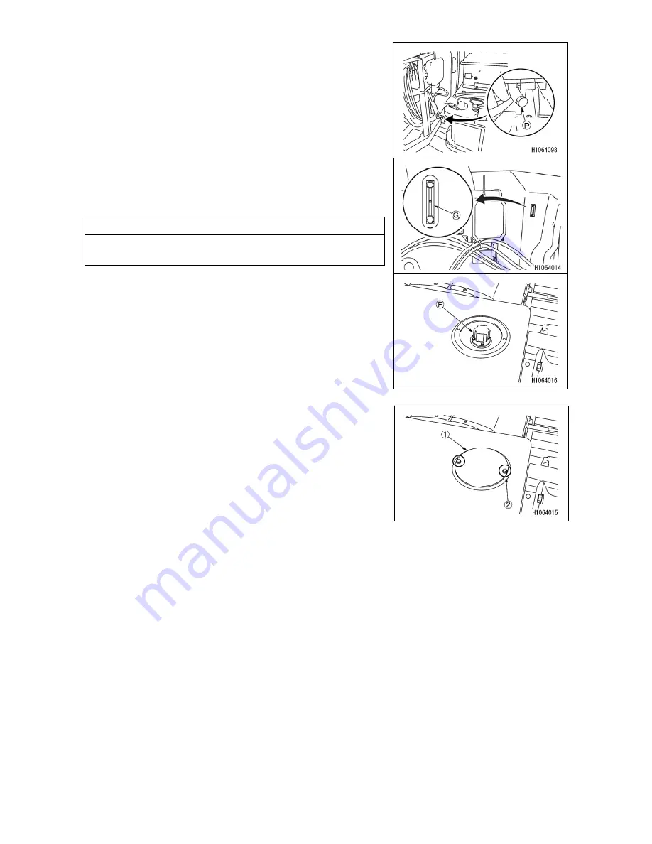
6. Place a drain pan directly underneath the drain plug
(P)
to receive drained oil.
7. Turn the drain plug
(P)
slowly to avoid splashing oil on
yourself, and drain oil.
8. Check the drained oil and if it contains an unacceptable
amount of metal particles or foreign matter, contact us
or our sales service agent.
9. Install and tighten the drain plug
(P)
securely.
10. Feed hydraulic oil through the filler port to the level
where you can see the oil on the oil level gauge (G).
11. Securely close the air filter
(F)
after refilling.
NOTES
Wipe away cleanly whenever the oil spills.
12. Place the cover (1) on the original position and tighten
the mounting bolts (2) (3 bolts) securely.
13.
See “OPERATION 2.19 BOOM DERRICKING
OPERATION” and lower the boom to the stowage
position and stop the engine.
14. Bleed the air according to the following sequence.
(1) Start the engine only after piping and hydraulic equipment are filled with oil.
After engine start, continue to run the engine at low idle for 10 minutes.
(2) While keeping the engine speed low, slightly operate each control lever to operate each
cylinder and winch motor slowly.
Do not operate the boom hoisting cylinder and telescopic boom cylinder to the stroke end,
but stop them at a position approximately 100 mm before the stroke end.
Repeat this 4 to 5 times.
(3) See “OPERATION 2.14 OUTRIGGER SETTING OPERATION” and make the outrigger
cylinder telescope in a condition that the machine does not float.
When making the outrigger cylinder telescope, do not operate it to the stroke end, but
stop it at a position approximately 100 mm before the stroke end.
Repeat this 4 to 5 times.
15. See “OPERATION 2.24 OUTRIGGER STOWAGE OPERATION” to stow all the outriggers.
Summary of Contents for MC815C
Page 2: ......
Page 30: ...20 This Page Intentionally Left Blank...
Page 73: ...63 3 Total load chart 106 2186300...
Page 75: ...65 9 Precautions when using 106 2186600...
Page 76: ...66...
Page 82: ...72 This Page Intentionally Left Blank...
Page 197: ...187 Remote control menu...
Page 254: ...244 This Page Intentionally Left Blank...
Page 314: ...304...
Page 338: ...328 This Page Intentionally Left Blank...
Page 343: ...333 2 SPECIFICATION DIMENSIONAL DRAWING...
Page 344: ...334 3 DIMENSIONAL DRAWING OF OUTRIGGER WIDTH...
Page 357: ...347 5 WORKING RADIUS LIFTING HEIGHT...
Page 362: ...352 1 Diagram of fly jib working range chart 106 2189200...
Page 397: ...387 9 4 WORKING RADIUS LIFTING HEIGHT...
Page 398: ...388 This Page Intentionally Left Blank...
Page 402: ...392 1 Searcher hook working range diagram 106 2189200...
Page 424: ...414 9 4 WORKING RADIUS LIFTING HEIGHT...
Page 426: ......