


197
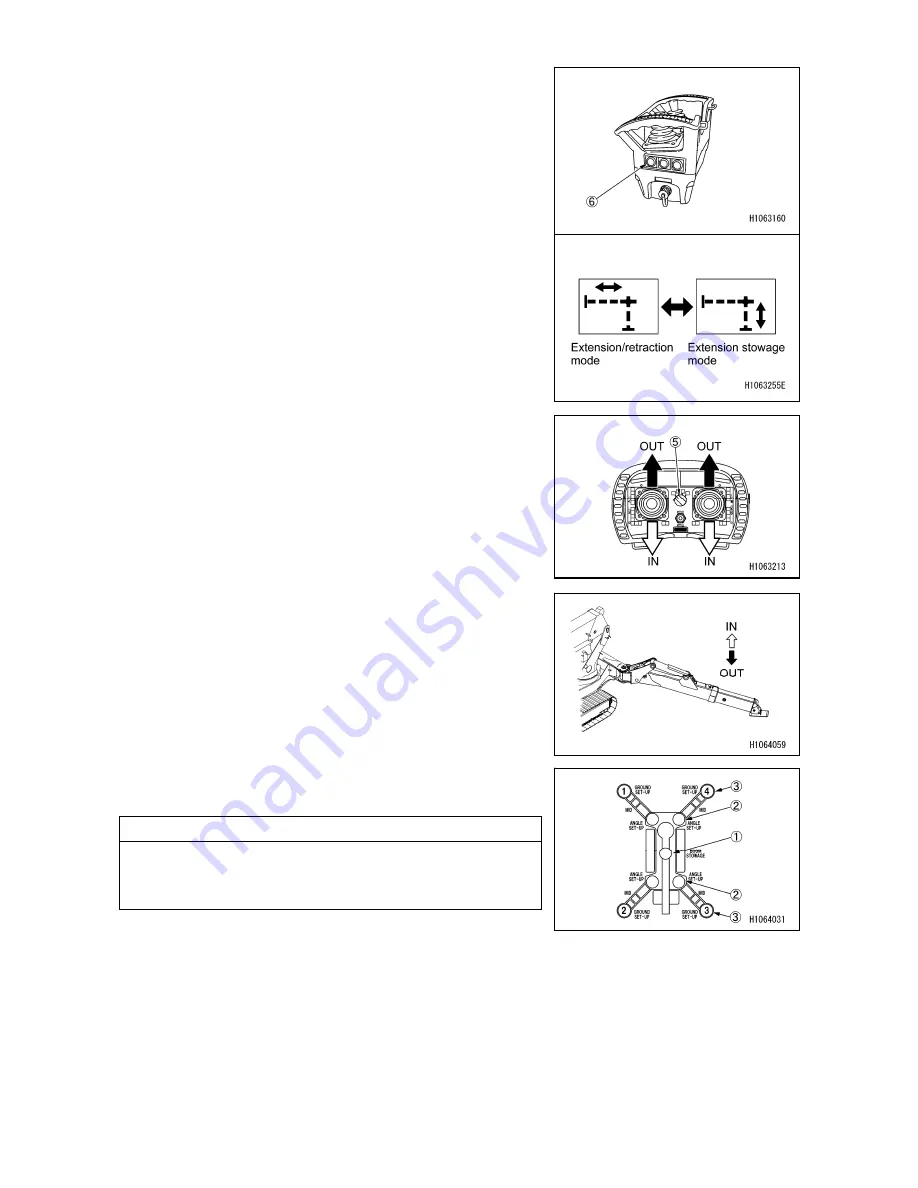
4. Change the mode to Extension stowage with the Speed
selector/Outrigger select switch (6) for the transmitter.
5. When the grounding cylinder has been extended and
the adapter has been grounded by manipulating the
control lever, release your hand from the operation
lever.
Repeat this step to gradually lower the machine until
the crawler belts are completely grounded.
6. After the right and left crawler belts come to complete
contact with the ground, further operate the control
lever.
When the grounding cylinder has been completely
retracted and the top box is raised to the maximum
height, release your finger from the outrigger switch.
7. Make sure that the four outrigger grounding lamps (3)
on the outrigger indicator are blinking in red.
NOTES
On the monitor, the crane stowage lamp (1) is lit in yellow,
and the four outrigger extension lamps (2) and the four
outrigger grounding lamps (3) are blinking in red.
Summary of Contents for MC815C
Page 2: ......
Page 30: ...20 This Page Intentionally Left Blank...
Page 73: ...63 3 Total load chart 106 2186300...
Page 75: ...65 9 Precautions when using 106 2186600...
Page 76: ...66...
Page 82: ...72 This Page Intentionally Left Blank...
Page 197: ...187 Remote control menu...
Page 254: ...244 This Page Intentionally Left Blank...
Page 314: ...304...
Page 338: ...328 This Page Intentionally Left Blank...
Page 343: ...333 2 SPECIFICATION DIMENSIONAL DRAWING...
Page 344: ...334 3 DIMENSIONAL DRAWING OF OUTRIGGER WIDTH...
Page 357: ...347 5 WORKING RADIUS LIFTING HEIGHT...
Page 362: ...352 1 Diagram of fly jib working range chart 106 2189200...
Page 397: ...387 9 4 WORKING RADIUS LIFTING HEIGHT...
Page 398: ...388 This Page Intentionally Left Blank...
Page 402: ...392 1 Searcher hook working range diagram 106 2189200...
Page 424: ...414 9 4 WORKING RADIUS LIFTING HEIGHT...
Page 426: ......