


140
2.3 OPERATIONS AND CHECKS AFTER STARTING ENGINE
Never refuel (diesel fuel) while the engine is in operation.
Always stop the engine before refilling fuel.
• If any abnormal condition occurs in the machine during engine warm-up, immediately
push the engine emergency stop switch to bring the engine to an emergency stop.
Then, turn the starter switch key to the “OFF” position. The power supply of the
electric system is turned OFF.
• Always perform the warm-up operation. The motor needs adequate warm-up time
especially in cold climates.
Failure to warm the motor may result in a serious accident on account of slow reaction
of the travelling gear and crane from the operating levers.
• Crane operational check is necessary after motor warm-up.
Keep the hook block away from the boom to avoid interference or collision.
• Exercise caution to avoid contact between the boom, the operator and any personnel
whilst slewing it.
• If crane operational check detects an abnormal event, make an emergency stop
promptly and repair any relevant part.
A potential serious accident may occur if disregarded.
CAUTION
• The appropriate temperature of the hydraulic oil is 50 to 80°C.
Even when operating at low temperature by necessity, increase the temperature of the
hydraulic oil to about 20°C.
• Do not raise engine speed suddenly until the warm-up operation is done.
• When the engine has started, check to see if the “Battery charge monitor” and “Engine
hydraulic monitor” lamps are turned off.
Repair if any abnormality is found.
• Do not run the engine at low or high idling for 20 minutes or longer.
If the engine requires idling, occasionally apply a load to the engine, or run the engine
at a mid-speed idle.
When using the engine at low speed, increase the engine speed for about 5 minutes
once a day.
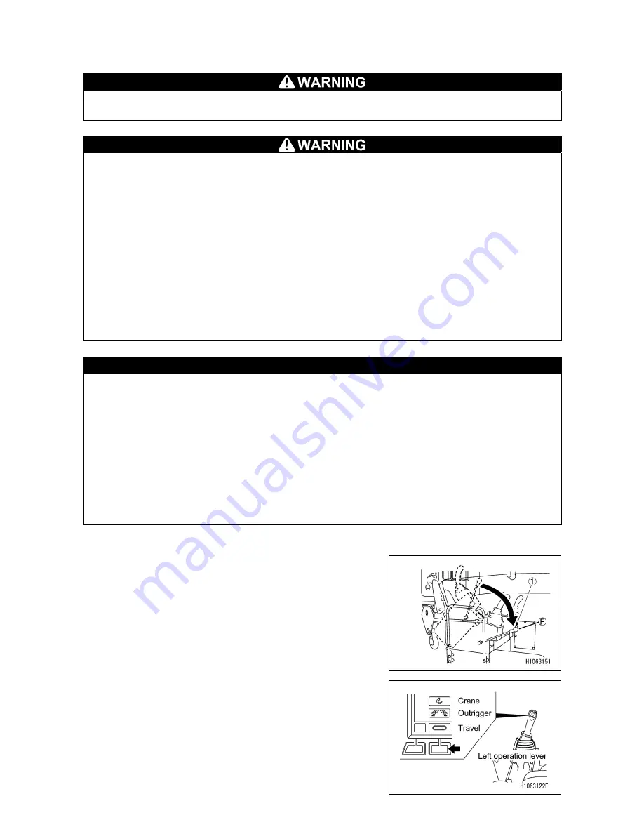
Perform the warm-up operation as follows once the engine
has started.
1. Release the lock lever (1) slowly and shift it into the free
(F) position.
2. With no load, let the engine idle for about 5 minutes.
3. Check if there is any abnormality with the engine
exhaust gas color, noise, and vibration.
Repair if any abnormality is found.
4. See “OPERATION 2.14 OUTRIGGER SETTING
OPERATION” to set the outriggers.
5. See “OPERATION 2.16 OPERATION BEFORE CRANE
WORK” to release the hook block from the stow
position.
Summary of Contents for MC815C
Page 2: ......
Page 30: ...20 This Page Intentionally Left Blank...
Page 73: ...63 3 Total load chart 106 2186300...
Page 75: ...65 9 Precautions when using 106 2186600...
Page 76: ...66...
Page 82: ...72 This Page Intentionally Left Blank...
Page 197: ...187 Remote control menu...
Page 254: ...244 This Page Intentionally Left Blank...
Page 314: ...304...
Page 338: ...328 This Page Intentionally Left Blank...
Page 343: ...333 2 SPECIFICATION DIMENSIONAL DRAWING...
Page 344: ...334 3 DIMENSIONAL DRAWING OF OUTRIGGER WIDTH...
Page 357: ...347 5 WORKING RADIUS LIFTING HEIGHT...
Page 362: ...352 1 Diagram of fly jib working range chart 106 2189200...
Page 397: ...387 9 4 WORKING RADIUS LIFTING HEIGHT...
Page 398: ...388 This Page Intentionally Left Blank...
Page 402: ...392 1 Searcher hook working range diagram 106 2189200...
Page 424: ...414 9 4 WORKING RADIUS LIFTING HEIGHT...
Page 426: ......