


12
[2] OUTRIGGER MAXIMUM EXTENSION
• Always place all outriggers securely before operating the crane.
Unless all of the outrigger monitor lamps are lit except for the boom stowing lamp,
interlock function works and, as a result, no crane operation can be performed.
• Outriggers should be set to the ground while watching leveling instrument so that the
machine is set horizontally.
Tilting the machine more than 3° activates alarm buzzer. To stop the buzzer, place the
machine horizontally.
• There are 3 outrigger modes N, M and P. For M and P mode see” Operation 1.2.1 [4]
MONITOR DISPLAY (CRANE MODE) [10] Hanging mode”.
N Mode: Unless outriggers are extended to maximum, work should be performed in
accordance with values shown in the “Use with outriggers extended to medium”
column or “Use with outriggers extended to minimum” column of the Rated Total Load
Chart.
Working under improper values may cause the machine to tip over. Be very careful.
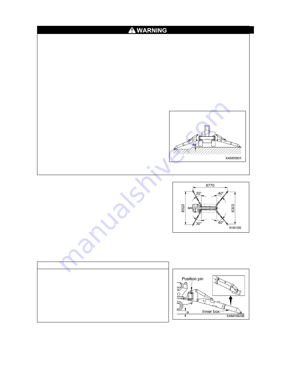
• Even with all the outriggers extended to maximum,
the outrigger width is decreased on uneven terrain
even if the dimension “a” in the figure on the right
is 50 mm. In such a case, work should be performed
in accordance with values shown in the “Use with
outriggers extended to medium” column of the
Rated Total Load Chart.
• Slewing 360° with a load lifted may expose the
machine to an unstable position. Even if the total
combined weight is within the rated total load,
reduce the working radius and traveling speed as
much as possible, and use sufficient care.
“Outriggers extended to maximum” in Rated Total Load
Chart represents the condition in the figure on the right.
Check that all of the outrigger monitor lamps are lit except
for the boom stowing lamp.
For N mode: Retraction of inner box extension to some
extent represents the condition other than the “Outriggers
Extended to Maximum”.
For M and P mode see” Operation 1.2.1 [4] MONITOR
DISPLAY (CRANE MODE) [10] Hanging mode”.
See “Operation 2.14 Outrigger Setup Operation” to set the
outriggers.
NOTES
“With outriggers extended to maximum” means that,
(1) The outrigger set up angle is set to the position pin
position (40° front and 30° rear).
(2) Inner boxes of all the outriggers are pulled out fully.
(3) All the outriggers are placed on level ground.
(4) Dimension
a
(distance between bottom of the
outrigger and bottom of the track) in the figure on the
right is approximately 50 mm.
The above represents “Outriggers extended to
maximum”.
Summary of Contents for MC815C
Page 2: ......
Page 30: ...20 This Page Intentionally Left Blank...
Page 73: ...63 3 Total load chart 106 2186300...
Page 75: ...65 9 Precautions when using 106 2186600...
Page 76: ...66...
Page 82: ...72 This Page Intentionally Left Blank...
Page 197: ...187 Remote control menu...
Page 254: ...244 This Page Intentionally Left Blank...
Page 314: ...304...
Page 338: ...328 This Page Intentionally Left Blank...
Page 343: ...333 2 SPECIFICATION DIMENSIONAL DRAWING...
Page 344: ...334 3 DIMENSIONAL DRAWING OF OUTRIGGER WIDTH...
Page 357: ...347 5 WORKING RADIUS LIFTING HEIGHT...
Page 362: ...352 1 Diagram of fly jib working range chart 106 2189200...
Page 397: ...387 9 4 WORKING RADIUS LIFTING HEIGHT...
Page 398: ...388 This Page Intentionally Left Blank...
Page 402: ...392 1 Searcher hook working range diagram 106 2189200...
Page 424: ...414 9 4 WORKING RADIUS LIFTING HEIGHT...
Page 426: ......