Installation Instructions
A4A9YG220B_111019
1-13
Completing the Installation
Checking Image Quality
[1]
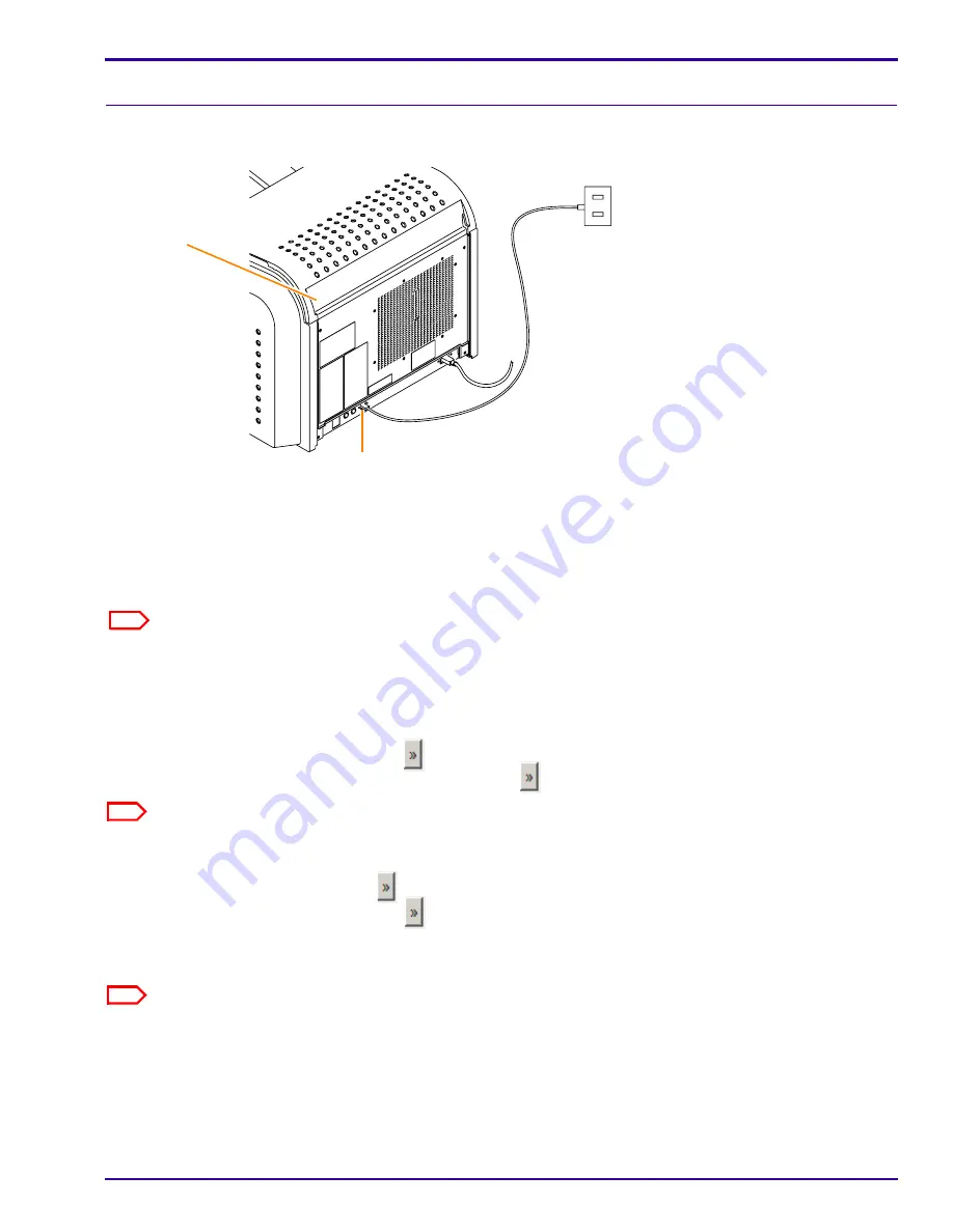
Connect the network cable to the:
• Network connector on the laser imager.
• Nearest active building network connector.
[2]
After the laser imager has completed the warm-up cycle, send an image from
each
modality that will print to
the laser imager.
[3]
If the image quality must be improved for a modality, optimize the images from that modality:
(a)
From the main screen, select
Wizards > Image Quality
.
(b)
Cancel all pending print jobs or wait until all print jobs are printed.
(c)
Under Optimization Steps, click
.
(d)
Send an image from the modality, and then click
.
Note
The image does not print until you click the button.
(e)
View the test print and visually select the optimal image.
(f)
Under Image Number, click
to select the number of your optimal image.
(g)
Under Optimization Steps, click
again to continue.
(h)
Check the status and result data near the bottom of the screen.
(i)
Send another image from the modality and check the print.
Note
If none of the images are optimal for the site, see Additional Service Procedures,
“Checking Image Quality”
.
[4]
Continue with
“Backing Up the System Configuration”
.
Laser Imager
Back Cover
Network Connector
Note
The default port No. of the laser imager is set to 5040.


