


Hardware Component Overview
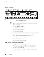
YELLOW ALARM
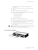
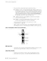
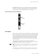
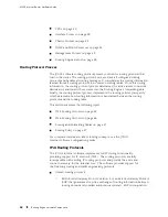
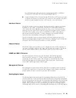
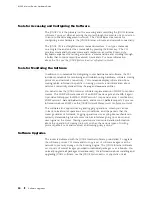
(see Figure 16). A system condition that causes the red or yellow
alarm LED to light on the craft interface also activates the corresponding alarm
relay contact. For instructions for attaching a device to the alarm relay contacts,
see “Connecting to an External Alarm-Reporting Device” on page 115.
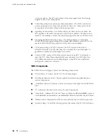
Figure 16: Alarm Relay Contacts and BITS Input Ports
BITS A
BITS B
LINK
RED ALARM
YELLOW
ALARM
LINK
1173
Alarm relay
contacts
BITS
input ports
NC
C
NO
NC
C
NO
Power System
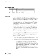
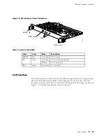
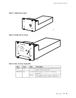
The router uses DC power. There are two load-sharing, pass-through power supplies
located at the bottom rear of the chassis, as shown in Figure 2. The power supplies
connect to the midplane, which distributes power to router components according
to their individual voltage requirements. When the power supplies are installed
and operational, they automatically share the electrical load. If a power supply
stops functioning for any reason, the remaining power supplies instantly begin
providing all the power the router needs for normal functioning and can provide
full power indefinitely.
Power supplies are hot-removable and hot-insertable, as described in
Field-Replaceable Units (FRUs) on page 4. To avoid electrical injury, carefully follow
the instructions in “Replacing a Power Supply” on page 197.
NOTE:
After powering off a power supply, wait at least 60 seconds before turning
it back on. After powering on a power supply, wait at least 60 seconds before
turning it off.
If the router is completely powered down when you power on the power supply,
the Routing Engine boots as the power supply completes its startup sequence. If
Power System
35
Summary of Contents for Internet Router M160
Page 12: ...M160 Internet Router Hardware Guide xii Table of Contents ...
Page 16: ...M160 Internet Router Hardware Guide xvi List of Figures ...
Page 18: ...M160 Internet Router Hardware Guide xviii List of Tables ...
Page 24: ...M160 Internet Router Hardware Guide xxiv Requesting Support ...
Page 26: ...2 Product Overview ...
Page 30: ...M160 Internet Router Hardware Guide 6 Safety Requirements Warnings and Guidelines ...
Page 66: ...M160 Internet Router Hardware Guide 42 Cable Management System ...
Page 80: ...M160 Internet Router Hardware Guide 56 Routing Engine Architecture ...
Page 82: ...58 Initial Installation ...
Page 104: ...M160 Internet Router Hardware Guide 80 Unpacking the Router ...
Page 148: ...M160 Internet Router Hardware Guide 124 Configuring the JUNOS Internet Software ...
Page 150: ...126 Hardware Maintenance Replacement and Troubleshooting Procedures ...
Page 242: ...M160 Internet Router Hardware Guide 218 Troubleshooting the Power System ...
Page 244: ...220 Appendixes ...
Page 292: ...M160 Internet Router Hardware Guide 268 Packing Components for Shipment ...
Page 301: ...Part 5 Index Index 277 ...
Page 302: ...278 Index ...


