Troubleshooting Hardware Components
LEDs on Hardware Components
LEDs on the faceplates of the following hardware components report their status:
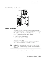
DC power supply—A green LED labeled
CB ON
, a blue one labeled
OUTPUT OK
,
and an amber one labeled
CB OFF
. The original power supply also has an amber
LED labeled
NO AIRFLOW
. For more information, see “Power Supply” on page 36.
MCS—A blue LED labeled
MASTER
, a green one labeled
OK
, and an amber one
labeled
FAIL
. For more information, see “MCS Components” on page 26.
PCG—A blue LED labeled
MASTER
, a green one labeled
OK
, and an amber one
labeled
FAIL
. For more information, see “PCG Components” on page 19.
PIC—Most PICs have an LED labeled
STATUS
on the PIC faceplate. Some PICs
have additional LEDs, often one per port. The meaning of the LED states differs
for various PICs. For more information, see the
M160 Internet Router PIC Guide
.
SFM—A green LED labeled
OK
and a red one labeled
FAIL
. For more
information, see “SFM Components” on page 20.
Chassis and Interface Alarm Messages
When the Routing Engine detects an alarm condition, it lights the red or
yellow alarm LED on the craft interface as appropriate, trips the corresponding
alarm relay contact on the CIP, and reports the cause of the alarm in the
craft interface LCD. To view a more detailed description of the alarm
cause, issue the
show chassis alarms
CLI command:
user@host> show chassis alarms
There are two classes of alarm messages:
Chassis alarms—Indicate a problem with a chassis component such as the
cooling system or power supplies, as described in Table 26.
Interface alarms—Indicate a problem with a specific network interface, as
described in Table 27.
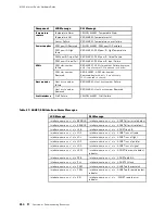
In both Table 26 and Table 27, the text in the column labeled “LCD Message”
appears in the LCD. The text in the column labeled “CLI Message” appears
in the output from the
show chassis alarms
command.
Table 26: Chassis Alarm Messages
Component
LCD Message
CLI Message
Fan Failure
RED ALARM -
fan name
Failure
Fan Removed
YELLOW ALARM -
fan name
Removed
Fans and
impellers
Fans Missing
RED ALARM - Too many fans missing or failing
Overview of Troubleshooting Resources
209
Summary of Contents for Internet Router M160
Page 12: ...M160 Internet Router Hardware Guide xii Table of Contents ...
Page 16: ...M160 Internet Router Hardware Guide xvi List of Figures ...
Page 18: ...M160 Internet Router Hardware Guide xviii List of Tables ...
Page 24: ...M160 Internet Router Hardware Guide xxiv Requesting Support ...
Page 26: ...2 Product Overview ...
Page 30: ...M160 Internet Router Hardware Guide 6 Safety Requirements Warnings and Guidelines ...
Page 66: ...M160 Internet Router Hardware Guide 42 Cable Management System ...
Page 80: ...M160 Internet Router Hardware Guide 56 Routing Engine Architecture ...
Page 82: ...58 Initial Installation ...
Page 104: ...M160 Internet Router Hardware Guide 80 Unpacking the Router ...
Page 148: ...M160 Internet Router Hardware Guide 124 Configuring the JUNOS Internet Software ...
Page 150: ...126 Hardware Maintenance Replacement and Troubleshooting Procedures ...
Page 242: ...M160 Internet Router Hardware Guide 218 Troubleshooting the Power System ...
Page 244: ...220 Appendixes ...
Page 292: ...M160 Internet Router Hardware Guide 268 Packing Components for Shipment ...
Page 301: ...Part 5 Index Index 277 ...
Page 302: ...278 Index ...

