Hardware Component Overview
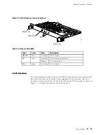
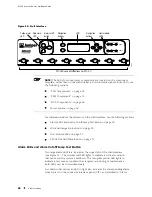
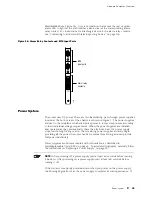
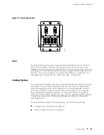
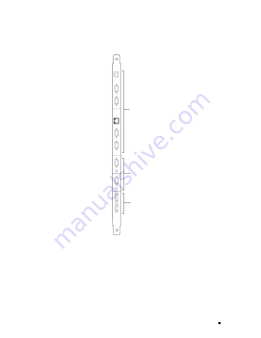
Figure 14: Connector Interface Panel
HOST
0
YEL=10Mb
GRN=100Mb
ACT
ETHERNET
ETHERNET
CONSOLE
CONSOLE
AUXILIARY
AUXILIARY
HOST
1
YEL=10Mb
GRN=100Mb
ACT
BITS A
BITS B
LINK
RED ALARM
YELLOW
ALARM
LINK
1204
Alarm relay
contacts
BITS
input ports
Routing
Engine ports
NC
C
NO
NC
C
NO
Routing Engine Management Ports
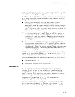
On the upper half of the CIP are two sets of ports for connecting the Routing
Engines to one or more external devices on which system administrators can issue
JUNOS command-line interface (CLI) commands to manage the router. The set of
ports labeled
HOST0
connects to the Routing Engine in the slot labeled
RE 0
, and the
set labeled
HOST1
connects to the Routing Engine in the slot labeled
RE 1
.
Connector Interface Panel (CIP)
33
Summary of Contents for Internet Router M160
Page 12: ...M160 Internet Router Hardware Guide xii Table of Contents ...
Page 16: ...M160 Internet Router Hardware Guide xvi List of Figures ...
Page 18: ...M160 Internet Router Hardware Guide xviii List of Tables ...
Page 24: ...M160 Internet Router Hardware Guide xxiv Requesting Support ...
Page 26: ...2 Product Overview ...
Page 30: ...M160 Internet Router Hardware Guide 6 Safety Requirements Warnings and Guidelines ...
Page 66: ...M160 Internet Router Hardware Guide 42 Cable Management System ...
Page 80: ...M160 Internet Router Hardware Guide 56 Routing Engine Architecture ...
Page 82: ...58 Initial Installation ...
Page 104: ...M160 Internet Router Hardware Guide 80 Unpacking the Router ...
Page 148: ...M160 Internet Router Hardware Guide 124 Configuring the JUNOS Internet Software ...
Page 150: ...126 Hardware Maintenance Replacement and Troubleshooting Procedures ...
Page 242: ...M160 Internet Router Hardware Guide 218 Troubleshooting the Power System ...
Page 244: ...220 Appendixes ...
Page 292: ...M160 Internet Router Hardware Guide 268 Packing Components for Shipment ...
Page 301: ...Part 5 Index Index 277 ...
Page 302: ...278 Index ...

