Hardware Component Overview
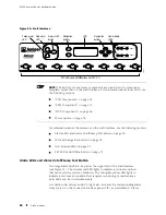
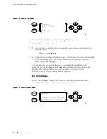
The lines in the display report the following information:
First line—Routing node name.
Second line—Number of active alarms.
Third and fourth lines—Individual alarm messages, with the most severe
condition shown first. The prefix on each line indicates whether the alarm is a
red (
R
) or yellow (
Y
) alarm.
For a list of alarm messages that can appear on the LCD, see “Chassis
and Interface Alarm Messages” on page 209.
Host Module LEDs
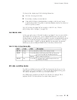
At the upper right corner of the craft interface (see Figure 11) are two sets of LEDs
that indicate host module status: the set labeled
HOST0
reports the status of the
Routing Engine in slot
RE 0
and MCS in slot
MCS 0
, and the set labeled
HOST1
reports
the status of the Routing Engine in slot
RE 1
and the MCS in slot
MCS 1
. Each set
includes three LEDs—a green one labeled
MASTER
, another green one labeled
ONLINE
, and a red one labeled
OFFLINE
. Table 10 describes the LED states.
Table 10: States for Host Module LEDs
Label
Color
State
Description
MASTER
Green
On steadily
Host module is functioning as master.
On steadily
Host module components (Routing Engine and
MCS) are installed and functioning normally.
ONLINE
Green
Blinking
Host module is starting up.
OFFLINE
Red
On steadily
One or both host module components are not
installed or have failed.
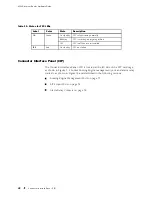
FPC LEDs and Offline Button
The LEDS and offline button for each FPC are located directly above it on the
craft interface, as shown in Figure 11. The red LED labeled
FAIL
and the green
LED labeled
OK
indicate FPC status, as described in Table 11.
The offline button, labeled with the FPC slot number (for example,
FPC2
),
prepares the FPC for removal from the router when pressed.
Craft Interface
31
Summary of Contents for Internet Router M160
Page 12: ...M160 Internet Router Hardware Guide xii Table of Contents ...
Page 16: ...M160 Internet Router Hardware Guide xvi List of Figures ...
Page 18: ...M160 Internet Router Hardware Guide xviii List of Tables ...
Page 24: ...M160 Internet Router Hardware Guide xxiv Requesting Support ...
Page 26: ...2 Product Overview ...
Page 30: ...M160 Internet Router Hardware Guide 6 Safety Requirements Warnings and Guidelines ...
Page 66: ...M160 Internet Router Hardware Guide 42 Cable Management System ...
Page 80: ...M160 Internet Router Hardware Guide 56 Routing Engine Architecture ...
Page 82: ...58 Initial Installation ...
Page 104: ...M160 Internet Router Hardware Guide 80 Unpacking the Router ...
Page 148: ...M160 Internet Router Hardware Guide 124 Configuring the JUNOS Internet Software ...
Page 150: ...126 Hardware Maintenance Replacement and Troubleshooting Procedures ...
Page 242: ...M160 Internet Router Hardware Guide 218 Troubleshooting the Power System ...
Page 244: ...220 Appendixes ...
Page 292: ...M160 Internet Router Hardware Guide 268 Packing Components for Shipment ...
Page 301: ...Part 5 Index Index 277 ...
Page 302: ...278 Index ...

