Chapter 4 VRM AND EBL FUNCTION
53
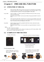
4.3 EXAMPLE OF EBL FUNCTION
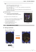
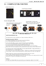
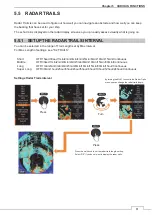
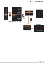
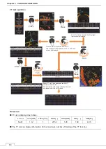
Example: EBL function.
How to change the EBL
Press the MULTI control, select
EBL1/2 and turn the MULTI control left
or right to change the EBL direction.
Target bearing is displayed.
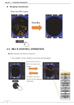
Press the EBL button, and turn the MULTI
control left or right to change the EBL
direction.
Or
᧦᧦᧦᧦
FOR REFERENCE
᧦᧦᧦᧦
ABOUT EBL/VRM FUNCTION
The target direction and range information can be measured by EBL and VRM function.
Bearing measurement method:
(1) The RELATIVE BEARING which is measured from own ship heading line.
(2) The TRUE BEARING which is measured from the north line.
Certainly, TRUE BEARING is calculated by RELATIVE BEARING and GYRO BEARING.
So, to calculate the TRUE BEARING is necessary a signal from GYRO or GPS compasses.
In case of no external bearing signal, display only RELATIVE BEARING mode.
Target tracking function (TT) and display AIS symbol is necessary the GYRO or GPS compass signal.
When GYRO or GPS compass signal is received, normally azimuth is measured from the north (TRUE AZIMUTH).
This radar scanner has a microwave BEAM WIDTH is about 4 degrees (NKE-2043), 2 degrees (NKE-2063A), 1.9
degrees (NKE-2103-4) or 1.2 degrees (NKE-2103-6).
So every target echo has more than 4 degrees, 2 degrees, 1.9 degrees or 1.2 degrees width for bearing direction.
For above reason, in case of read out the target azimuth, you need set EBL line to the center of the target echo.
RANGE of target echo in any azimuth can be measured by the VRM function from own ship.
Target echo size is proportion to pulse width which transmitted from own ship.
In case of MEASURE SHORT RANGE ECHO using VRM, you need set ring to the echo’s nearest point from own ship.
At that point, you can get the correct RANGE for any pulse width.
Floating:
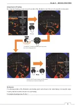
The base point of EBL/VRM can be set other than own ship position. Refer to "5.18.1 EBL."
㸩
㸩
㸫
㸫
Summary of Contents for JMA-3400 Series
Page 2: ......
Page 23: ...WARNING LABEL MOUNTING POINT xxi NKE 2103 4 4HS 6 6HS SCANNER UNIT NCD 2364 DISPLAY UNIT ...
Page 31: ...EQUIPMENT APPEARANCE xxix NKE 2043 SCANNER UNIT NKE 2063A AHS SCANNER UNIT ...
Page 32: ...EQUIPMENT APPEARANCE xxx NKE 2103 4 4HS 6 6HS SCANNER UNIT ...
Page 34: ...EQUIPMENT APPEARANCE xxxii Fuse ...
Page 48: ......
Page 51: ...Chapter 1 INSTALLATION 3 1 2 3 DIMENSIONAL DRAWING OF DISPLAY MOUNTING ...
Page 56: ...Chapter 1 INSTALLATION 8 FLUSH MOUNTING TEMPLATE Note Please note the paper size ...
Page 85: ...Chapter 2 THE BASIC OPERATION 37 2 2 OPERATION UNIT ࢫࣆ ձ ղ ճ մ յ ն շ ո չ պ վ տ ւ ջ ռ ս ր ց ...
Page 266: ...Chapter 13 SPECIFICATIONS 218 13 1 SCANNER DIMENSION 13 1 1 NKE 2043 ...
Page 270: ...Chapter 13 SPECIFICATIONS 222 13 2 DISPLAY DIMENSION 13 2 1 NCD 2364 ...
Page 283: ...235 Chapter 13 SPECIFICATIONS MEMO ...
Page 293: ...APPENDIX A 10 MEMO ...
Page 313: ......

