


Chapter 5 VARIOUS FUNCTIONS
87
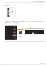
5.16.6 VIDEO NOISE REJECTION
This function rejects signals that assumed as noise and clutter in radar videos.
OFF: Turn off the noise rejection function, and display all signals. Targets are popped up from noise and
displayed like analog signals.
Level1: Reject the signals of definitely unwanted waves (noise and clutter). When detection of targets or
unwanted waves in no definite, signals are displayed. When detection of targets is definite, signals
are displayed.
Level2: Reject signals of definitely unwanted waves (noise and clutter). When detection of targets or
unwanted waves in no definite, the signals are displayed. When detection of targets is definite, the
signals are displayed. It will remove the signal that can be regarded as unnecessary wave of more
than level 1.
Level3: Select if “Level1” and “Level2” cannot reject signals enough.
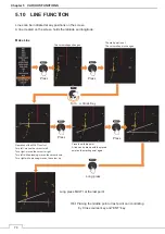
5.16.7 VIDEO LATITUDE
Select the dynamic range in which receiving signals are to be shown on the radar display.
Narrow: Narrow the dynamic range at short range.
Normal: Standard setting. The dynamic range varies depending on the actual range.
Wide1: Use this mode when rainy weather intensifies unwanted waves. The dynamic range is about
twice as wide as when Normal is selected.
Wide2: Use this mode when rain clouds remain even when using Wide1.
Max: Use this mode when you want to fine-tune the image for weak reflectors such as rain clouds.
Dynamic range is 2.5 ~ 5 times as large as normal.
Select Normal in standard, and Wide1 in rainy weather. Narrow clearly displays short-range videos when STC
is used in manual mode.
Summary of Contents for JMA-3400 Series
Page 2: ......
Page 23: ...WARNING LABEL MOUNTING POINT xxi NKE 2103 4 4HS 6 6HS SCANNER UNIT NCD 2364 DISPLAY UNIT ...
Page 31: ...EQUIPMENT APPEARANCE xxix NKE 2043 SCANNER UNIT NKE 2063A AHS SCANNER UNIT ...
Page 32: ...EQUIPMENT APPEARANCE xxx NKE 2103 4 4HS 6 6HS SCANNER UNIT ...
Page 34: ...EQUIPMENT APPEARANCE xxxii Fuse ...
Page 48: ......
Page 51: ...Chapter 1 INSTALLATION 3 1 2 3 DIMENSIONAL DRAWING OF DISPLAY MOUNTING ...
Page 56: ...Chapter 1 INSTALLATION 8 FLUSH MOUNTING TEMPLATE Note Please note the paper size ...
Page 85: ...Chapter 2 THE BASIC OPERATION 37 2 2 OPERATION UNIT ࢫࣆ ձ ղ ճ մ յ ն շ ո չ պ վ տ ւ ջ ռ ս ր ց ...
Page 266: ...Chapter 13 SPECIFICATIONS 218 13 1 SCANNER DIMENSION 13 1 1 NKE 2043 ...
Page 270: ...Chapter 13 SPECIFICATIONS 222 13 2 DISPLAY DIMENSION 13 2 1 NCD 2364 ...
Page 283: ...235 Chapter 13 SPECIFICATIONS MEMO ...
Page 293: ...APPENDIX A 10 MEMO ...
Page 313: ......