


Chapter 1 INSTALLATION
16
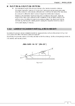
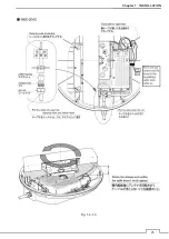
Others
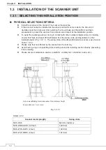
The design of the mounting platform for the scanner should take into account the
vibration requirements
defined by IEC 60945.
Vibration
Frequency
2 to 13.2 Hz
13.2 Hz to 100 Hz
Amplitude
+/-1 mm +/-10 %
Acceleration
7m/s
2
constant
z
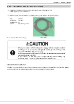
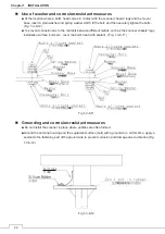
All installations should facilitate protection of equipment, including cabling, from
damage.
z
The cables should be kept as short as possible to minimize attenuation of the signal.
z
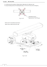
Crossing of cables should be done at right angles(90°) to minimize magnetic field
coupling.
z
Install the radar cable as far as from the cables of other radio equipment in order to
prevent other radio equipment from interfering with the radar operations. Especially
inter-wiring cables between scanner unit and display unit of the radar should not be
run parallel with the cables of other radio equipment.
z
Cable should not be exposed sharp bends.
z
Ensure that the equipment is grounded.
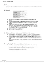
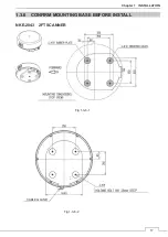
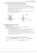
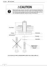
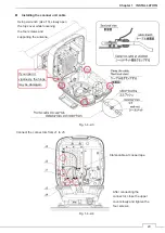
Maintain a flat level surface on which to install the scanner
z
Use sufficiently thick steel material and reinforcement material for the scanner's installation
surface (mount base) to reduce vibration and impact. Keep the mount base flat and smooth.
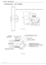
z
If there is a partial gap between the mount base and the scanner chassis's legs, work on the
installation surface so that it becomes flat and smooth, or make adjustments by inserting metal
shims.
If a gap exists and the scanner is tightly clamped, the chassis will distort and become damaged
by vibration.
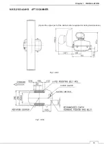
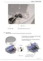
Avoid using vibration-proof rubber and resin
z
Do not insert an elastic body, such as vibration-proof rubber or resin, between the
mount base and the scanner chassis legs. If rubber or resin is inserted, the amplitude
of vibration increases, resulting in the possibility of damage to the scanner.
Furthermore, if installation bolts become loose due to deterioration of rubber or resin,
the scanner may be damaged or fall from its mount.
Summary of Contents for JMA-3400 Series
Page 2: ......
Page 23: ...WARNING LABEL MOUNTING POINT xxi NKE 2103 4 4HS 6 6HS SCANNER UNIT NCD 2364 DISPLAY UNIT ...
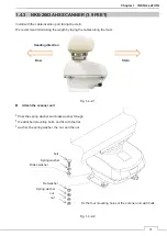
Page 31: ...EQUIPMENT APPEARANCE xxix NKE 2043 SCANNER UNIT NKE 2063A AHS SCANNER UNIT ...
Page 32: ...EQUIPMENT APPEARANCE xxx NKE 2103 4 4HS 6 6HS SCANNER UNIT ...
Page 34: ...EQUIPMENT APPEARANCE xxxii Fuse ...
Page 48: ......
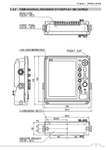
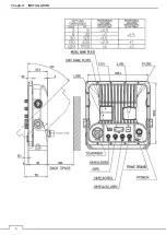
Page 51: ...Chapter 1 INSTALLATION 3 1 2 3 DIMENSIONAL DRAWING OF DISPLAY MOUNTING ...
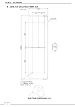
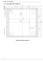
Page 56: ...Chapter 1 INSTALLATION 8 FLUSH MOUNTING TEMPLATE Note Please note the paper size ...
Page 85: ...Chapter 2 THE BASIC OPERATION 37 2 2 OPERATION UNIT ࢫࣆ ձ ղ ճ մ յ ն շ ո չ պ վ տ ւ ջ ռ ս ր ց ...
Page 266: ...Chapter 13 SPECIFICATIONS 218 13 1 SCANNER DIMENSION 13 1 1 NKE 2043 ...
Page 270: ...Chapter 13 SPECIFICATIONS 222 13 2 DISPLAY DIMENSION 13 2 1 NCD 2364 ...
Page 283: ...235 Chapter 13 SPECIFICATIONS MEMO ...
Page 293: ...APPENDIX A 10 MEMO ...
Page 313: ......