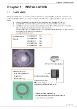


Chapter 1 INSTALLATION
15
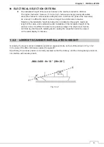
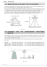
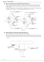
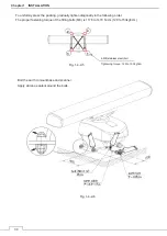
When installing two scanners, provide a height difference so that those two scanners do not enter each
other's vertical beam width range.
To avoid interference with other equipment and to prevent radio noise from generating, do not place the VHF
antenna, GPS antenna, and INMARSAT's dome within the range of the vertical beam width. Keep a record of
installation height data. The data is necessary for the initial setting of the display unit.
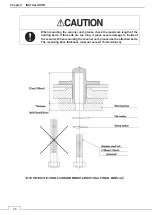
Magnetron which has strong magnetic force is included in the scanner. Install the scanner at least 3 meters
away from nautical instruments including magnetic compasses and chronometers.
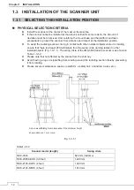
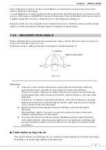
1.3.5 ENSURING VIEW ANGLE
Minimize the blind sector, and ensure the adequate view angle so that the blind sector does not exist in the
range 22.5° from side to rear (Fig. 1-3-5).
Specifically, ensure a sufficient view field in the straight front (relative bearing 0°).
Fig. 1-3-5
Reference:
z
If there is a concern that structural objects existing within the vertical beam width may
generate false images, equip the structural objects with a radio wave absorber.
(There are two types of absorbers: broadband type having no specific resonant frequency
and narrowband type which can absorb a band with a specific frequency. Use those where
applicable.)
Furthermore, it is effective to install a metal reflector, which reflects radio waves upwardly,
between the scanner and a structural object so that the radar's radio wave will not directly
come in contact with the structural object.
z
Because most radio wave absorbers have poor durability, some must be replaced
every year.
When installing a reflector, the area to the rear of the reflector becomes a blind sector.
Therefore, minimize the size of the reflector.
z
The above procedures for selecting a scanner installation position are described based
on the radar's scanner. Comprehensively select the scanner position by considering other
scanners' installation procedure manual, hull's structure, strength of the selected position,
and vibration.
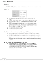
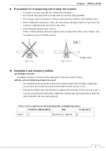
Ŷ
Confirmation during test run
If the scanner vibrates a lot during test run, try to reduce or prevent vibration by reinforcing the scanner
mount base or using wire stays attached to the radar mast.
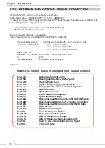
Summary of Contents for JMA-3400 Series
Page 2: ......
Page 23: ...WARNING LABEL MOUNTING POINT xxi NKE 2103 4 4HS 6 6HS SCANNER UNIT NCD 2364 DISPLAY UNIT ...
Page 31: ...EQUIPMENT APPEARANCE xxix NKE 2043 SCANNER UNIT NKE 2063A AHS SCANNER UNIT ...
Page 32: ...EQUIPMENT APPEARANCE xxx NKE 2103 4 4HS 6 6HS SCANNER UNIT ...
Page 34: ...EQUIPMENT APPEARANCE xxxii Fuse ...
Page 48: ......
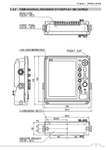
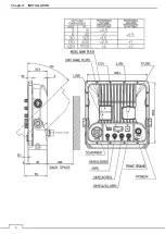
Page 51: ...Chapter 1 INSTALLATION 3 1 2 3 DIMENSIONAL DRAWING OF DISPLAY MOUNTING ...
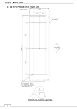
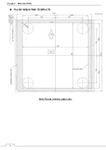
Page 56: ...Chapter 1 INSTALLATION 8 FLUSH MOUNTING TEMPLATE Note Please note the paper size ...
Page 85: ...Chapter 2 THE BASIC OPERATION 37 2 2 OPERATION UNIT ࢫࣆ ձ ղ ճ մ յ ն շ ո չ պ վ տ ւ ջ ռ ս ր ց ...
Page 266: ...Chapter 13 SPECIFICATIONS 218 13 1 SCANNER DIMENSION 13 1 1 NKE 2043 ...
Page 270: ...Chapter 13 SPECIFICATIONS 222 13 2 DISPLAY DIMENSION 13 2 1 NCD 2364 ...
Page 283: ...235 Chapter 13 SPECIFICATIONS MEMO ...
Page 293: ...APPENDIX A 10 MEMO ...
Page 313: ......