


204
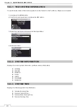
Chapter 10 MAINTENANCE AND CHECK
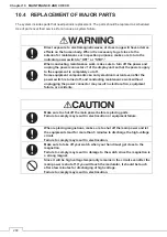
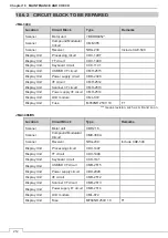
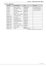
10.4 REPLACEMENT OF MAJOR PARTS
The system includes parts that need periodic replacement. The parts should be replaced as scheduled.
Use of parts over their service life can cause a system failure.
Direct exposure to electromagnetic waves at close range will have adverse
effects on the human body. When it is necessary to get close to the
antenna for maintenance or inspection purposes, make sure to turn the
indicator power switch to “OFF” or “STBY.”
When conducting maintenance work, make sure to turn off the power and
unplug the power connector J1 of the display unit so that the power supply
to the equipment is completely cut off.
Some equipment components can carry electrical current even after the
power switch is turned off, and conducting maintenance work without
unplugging the power connector may result in electrocution, equipment
failure, or accidents.
Make sure to shut off the main power before replacing parts.
Failure to comply may result in electrocution or equipment failure.
When replacing magnetrons, make sure to shut off the main power and let
the equipment stand for more than 5 minutes to discharge the high-voltage
circuit.
Failure to comply may result in electrocution.
Make sure to take off your watch when your hand must get close to the
magnetron.
Failure to comply may result in damage to the watch since the magnetron is
a strong magnet.
Since it will be high voltage temporarily remains in the circuit even after the
main power is shut off.
If you will touch the modulator, it should be touch
after a few minutes for discharging of high voltage.
Failure to comply may result in electrocution.
Summary of Contents for JMA-3400 Series
Page 2: ......
Page 23: ...WARNING LABEL MOUNTING POINT xxi NKE 2103 4 4HS 6 6HS SCANNER UNIT NCD 2364 DISPLAY UNIT ...
Page 31: ...EQUIPMENT APPEARANCE xxix NKE 2043 SCANNER UNIT NKE 2063A AHS SCANNER UNIT ...
Page 32: ...EQUIPMENT APPEARANCE xxx NKE 2103 4 4HS 6 6HS SCANNER UNIT ...
Page 34: ...EQUIPMENT APPEARANCE xxxii Fuse ...
Page 48: ......
Page 51: ...Chapter 1 INSTALLATION 3 1 2 3 DIMENSIONAL DRAWING OF DISPLAY MOUNTING ...
Page 56: ...Chapter 1 INSTALLATION 8 FLUSH MOUNTING TEMPLATE Note Please note the paper size ...
Page 85: ...Chapter 2 THE BASIC OPERATION 37 2 2 OPERATION UNIT ࢫࣆ ձ ղ ճ մ յ ն շ ո չ պ վ տ ւ ջ ռ ս ր ց ...
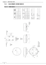
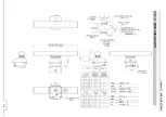
Page 266: ...Chapter 13 SPECIFICATIONS 218 13 1 SCANNER DIMENSION 13 1 1 NKE 2043 ...
Page 270: ...Chapter 13 SPECIFICATIONS 222 13 2 DISPLAY DIMENSION 13 2 1 NCD 2364 ...
Page 283: ...235 Chapter 13 SPECIFICATIONS MEMO ...
Page 293: ...APPENDIX A 10 MEMO ...
Page 313: ......