


Chapter 5 VARIOUS FUNCTIONS
93
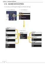
5.19 SET OWN SHIP MOVEMENT
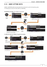
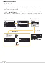
TM/RM: Switches between true and relative motion display modes. The bearing signal input is required
to display true motion.
In the true motion display mode, the own ship’s position on the radar screen moves
depending on its speed and course and the influence of the current. Land and other fixed
targets are fixed on the radar screen and only actually moving targets move on the radar
screen.
Bearing mode: Select the azimuth of the radar video.
The bearing signal input is required to display N-UP/C-UP.
䐡
Select each menu.
㻌
TM/RM
䐟
Press the MENU button.
㻌
䐠
Select “Set Own Ship Movement.”
㻌
Bearing Mode
Summary of Contents for JMA-3400 Series
Page 2: ......
Page 23: ...WARNING LABEL MOUNTING POINT xxi NKE 2103 4 4HS 6 6HS SCANNER UNIT NCD 2364 DISPLAY UNIT ...
Page 31: ...EQUIPMENT APPEARANCE xxix NKE 2043 SCANNER UNIT NKE 2063A AHS SCANNER UNIT ...
Page 32: ...EQUIPMENT APPEARANCE xxx NKE 2103 4 4HS 6 6HS SCANNER UNIT ...
Page 34: ...EQUIPMENT APPEARANCE xxxii Fuse ...
Page 48: ......
Page 51: ...Chapter 1 INSTALLATION 3 1 2 3 DIMENSIONAL DRAWING OF DISPLAY MOUNTING ...
Page 56: ...Chapter 1 INSTALLATION 8 FLUSH MOUNTING TEMPLATE Note Please note the paper size ...
Page 85: ...Chapter 2 THE BASIC OPERATION 37 2 2 OPERATION UNIT ࢫࣆ ձ ղ ճ մ յ ն շ ո չ պ վ տ ւ ջ ռ ս ր ց ...
Page 266: ...Chapter 13 SPECIFICATIONS 218 13 1 SCANNER DIMENSION 13 1 1 NKE 2043 ...
Page 270: ...Chapter 13 SPECIFICATIONS 222 13 2 DISPLAY DIMENSION 13 2 1 NCD 2364 ...
Page 283: ...235 Chapter 13 SPECIFICATIONS MEMO ...
Page 293: ...APPENDIX A 10 MEMO ...
Page 313: ......