


BEFORE OPERATION
xi
BEFORE OPERATION
PICTORIAL INDICATION
Various pictorial indications are included in this manual and are shown on these equipment so
that you can operate them safety and correctly and prevent any danger to you and/or to other
persons and any damage to your property during operation. Such indications and their
meanings are as follows.
Understand them before you read this manual.
DANGER
This indication is shown where incorrect equipment
operation due to negligence may cause death or
serious injuries.
WARNING
This indication is shown where any person is
supposed to be in danger of being killed or seriously
injured if this indication is neglected and these
equipment are not operated correctly.
CAUTION
This indication is shown where any person is
supposed to be injured or any property damage is
supposed to occur if this indication is neglected and
these equipment are not operated correctly.
EXAMPLES OF PICTORIAL INDICATION
Electric
Shock
The
U
mark represents CAUTION (including DANGER and
WARNING).
Detailed contents of CAUTION ("Electric Shock" in the
example on the left) is shown in the mark.
Disassembling
Prohibited
Prohibited
The
;
mark represents prohibition.
Detailed contents of the prohibited action ("Disassembling
Prohibited" in the example on the left) is shown in the mark.
Disconnect the
power plug
Instruction
The
z
mark represents instruction.
Detailed contents of the instruction ("Disconnect the power
plug" in the example on the left) is shown in the mark.
Summary of Contents for JMA-3400 Series
Page 2: ......
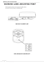
Page 23: ...WARNING LABEL MOUNTING POINT xxi NKE 2103 4 4HS 6 6HS SCANNER UNIT NCD 2364 DISPLAY UNIT ...
Page 31: ...EQUIPMENT APPEARANCE xxix NKE 2043 SCANNER UNIT NKE 2063A AHS SCANNER UNIT ...
Page 32: ...EQUIPMENT APPEARANCE xxx NKE 2103 4 4HS 6 6HS SCANNER UNIT ...
Page 34: ...EQUIPMENT APPEARANCE xxxii Fuse ...
Page 48: ......
Page 51: ...Chapter 1 INSTALLATION 3 1 2 3 DIMENSIONAL DRAWING OF DISPLAY MOUNTING ...
Page 56: ...Chapter 1 INSTALLATION 8 FLUSH MOUNTING TEMPLATE Note Please note the paper size ...
Page 85: ...Chapter 2 THE BASIC OPERATION 37 2 2 OPERATION UNIT ࢫࣆ ձ ղ ճ մ յ ն շ ո չ պ վ տ ւ ջ ռ ս ր ց ...
Page 266: ...Chapter 13 SPECIFICATIONS 218 13 1 SCANNER DIMENSION 13 1 1 NKE 2043 ...
Page 270: ...Chapter 13 SPECIFICATIONS 222 13 2 DISPLAY DIMENSION 13 2 1 NCD 2364 ...
Page 283: ...235 Chapter 13 SPECIFICATIONS MEMO ...
Page 293: ...APPENDIX A 10 MEMO ...
Page 313: ......