


Chapter 5 VARIOUS FUNCTIONS
62
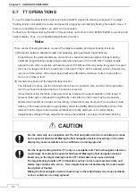
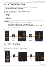
5.6 AIS
OPERATIONS
AIS is shows the target's information on the radar display, using other ship's information sent out from the AIS
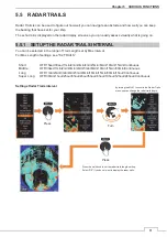
unit. Furthermore, the AIS displaying function of this unit does not conform to IE C62388 / 62288 in operation
and symbol display. Thus, it is a simplified AIS displaying function.
Reference:
To use this function, ship’s heading, position and AIS information are required.
For AIS function of settings, see "5.24 AIS/TT."
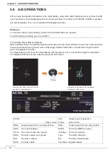
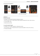
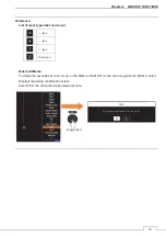
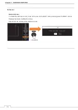
The specified target data is displayed.
BRG and RNG shows the relative positional information which is observed from the own ship. COG and SOG
shows ground speed and ground course of the target. Position information is measured through the GPS
which is equipped to the ship.
The target data will remain on the radar display until the target is lost, or until another target is designated.
The displayed AIS data can be closed by press the CLR button.
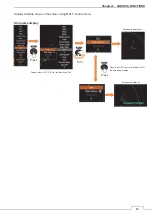
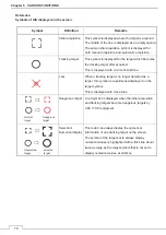
AIS No.
CPA
Closest point of approach.
Ship’s name TCPA:
Time to CPA.
BRG:
Target bearing from own ship direction.
RNG:
Target range from own ship position.
HDG:
The ship’s heading.
MMSI:
The ship’s MMSI (Country).
COG:
The ship’s course over ground.
Call Sign
The ship’s call sign.
SOG:
The ship’s speed over ground.
Type
The ship’s ship type.
ROT:
The ship’s rotation.
B/L:
The ship’s beam/length.
Draft:
The ship’s draft.
The ship’s navigation status
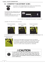
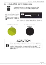
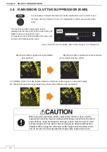
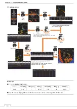
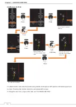
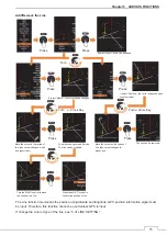
Press
Move the cross cursor to the AIS for which
you want to check information.
Information on the selected AIS is displayed
at the bottom of the screen.
Summary of Contents for JMA-3400 Series
Page 2: ......
Page 23: ...WARNING LABEL MOUNTING POINT xxi NKE 2103 4 4HS 6 6HS SCANNER UNIT NCD 2364 DISPLAY UNIT ...
Page 31: ...EQUIPMENT APPEARANCE xxix NKE 2043 SCANNER UNIT NKE 2063A AHS SCANNER UNIT ...
Page 32: ...EQUIPMENT APPEARANCE xxx NKE 2103 4 4HS 6 6HS SCANNER UNIT ...
Page 34: ...EQUIPMENT APPEARANCE xxxii Fuse ...
Page 48: ......
Page 51: ...Chapter 1 INSTALLATION 3 1 2 3 DIMENSIONAL DRAWING OF DISPLAY MOUNTING ...
Page 56: ...Chapter 1 INSTALLATION 8 FLUSH MOUNTING TEMPLATE Note Please note the paper size ...
Page 85: ...Chapter 2 THE BASIC OPERATION 37 2 2 OPERATION UNIT ࢫࣆ ձ ղ ճ մ յ ն շ ո չ պ վ տ ւ ջ ռ ս ր ց ...
Page 266: ...Chapter 13 SPECIFICATIONS 218 13 1 SCANNER DIMENSION 13 1 1 NKE 2043 ...
Page 270: ...Chapter 13 SPECIFICATIONS 222 13 2 DISPLAY DIMENSION 13 2 1 NCD 2364 ...
Page 283: ...235 Chapter 13 SPECIFICATIONS MEMO ...
Page 293: ...APPENDIX A 10 MEMO ...
Page 313: ......