


233
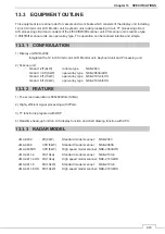
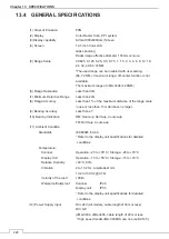
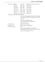
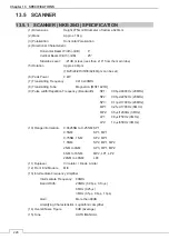
Chapter 13 SPECIFICATIONS
13.7 INPUT/ OUTPUT SIGNAL
13.7.1 INPUT ENABLE SIGNAL
࣭
NMEA0183 input sentences
(1) Navigation equipment
Lat/Lon:
GGA>RMC>RMA>GNS>GLL
SOG/COG: RMC>RMA>VTG
Log speed:
VBW>VHW
HEADING: THS>HDT>HDG>HDM
DEPTH:
DPT>DBT
WATER TEMP: MTW
ROT:
ROT
RUDDER: RSA
AIS:
VDM,
VDO,
ALR
WIND:
MWV>VWT,
VWR
WAYPOINT: RMB>BWC>BWR
(2) Bearing signal THS>HDT>HDG>HDM
(3) Speed signal VBW, VHW
࣭
CAN input PGN
Data
CAN
PGN
Contents
Log speed
128259
Speed, water referenced
Depth
128267
Including relative to the transducer and offset.
Cross Track Error
129283
Provides the magnitude of position error
perpendicular to the desired course.
Navigation data
129284
An essential navigation data for following a route.
WP information
129285
Route and WP data ahead in the Active Route
COG/SOG
130578
COG and SOG, rapid update
Longitude/Latitude
127250
GNSS position data
Water Temp
130310
Water temperature
Summary of Contents for JMA-3400 Series
Page 2: ......
Page 23: ...WARNING LABEL MOUNTING POINT xxi NKE 2103 4 4HS 6 6HS SCANNER UNIT NCD 2364 DISPLAY UNIT ...
Page 31: ...EQUIPMENT APPEARANCE xxix NKE 2043 SCANNER UNIT NKE 2063A AHS SCANNER UNIT ...
Page 32: ...EQUIPMENT APPEARANCE xxx NKE 2103 4 4HS 6 6HS SCANNER UNIT ...
Page 34: ...EQUIPMENT APPEARANCE xxxii Fuse ...
Page 48: ......
Page 51: ...Chapter 1 INSTALLATION 3 1 2 3 DIMENSIONAL DRAWING OF DISPLAY MOUNTING ...
Page 56: ...Chapter 1 INSTALLATION 8 FLUSH MOUNTING TEMPLATE Note Please note the paper size ...
Page 85: ...Chapter 2 THE BASIC OPERATION 37 2 2 OPERATION UNIT ࢫࣆ ձ ղ ճ մ յ ն շ ո չ պ վ տ ւ ջ ռ ս ր ց ...
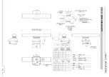
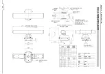
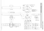
Page 266: ...Chapter 13 SPECIFICATIONS 218 13 1 SCANNER DIMENSION 13 1 1 NKE 2043 ...
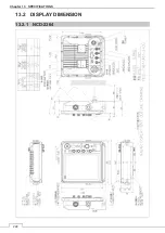
Page 270: ...Chapter 13 SPECIFICATIONS 222 13 2 DISPLAY DIMENSION 13 2 1 NCD 2364 ...
Page 283: ...235 Chapter 13 SPECIFICATIONS MEMO ...
Page 293: ...APPENDIX A 10 MEMO ...
Page 313: ......