


Chapter 3 ADJUST THE RADAR ECHO
48
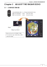
3.2 SENSITIVITY ADJUSTMENT (GAIN)
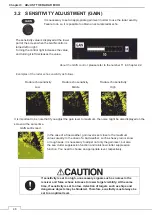
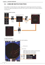
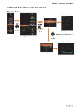
Radar echo sensitivity Radar echo sensitivity Radar echo sensitivity
Low
Middle High
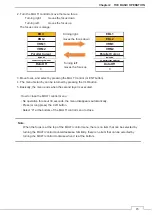
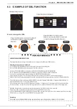
It is important to be note that if you adjust the gain level to maximum, the noise might be also displayed on the
screen at the same time.
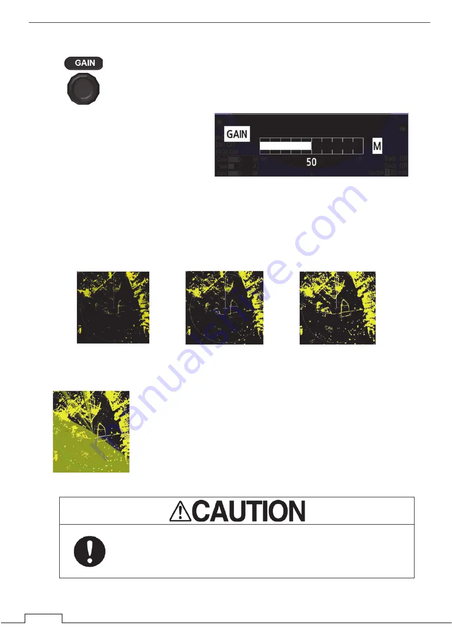
GAIN set Exceed
If sensitivity is set too high, unnecessary signals such as noises in the
receiver and false echoes increase to lower target visibility. At the same
time, if sensitivity is set too low, detection of targets such as ships and
dangerous objects may be hindered. Therefore, sensitivity must always be
set to an optimal level.
The sensitivity value is displayed at the lower
part of the screen when the GAIN control is
turned left or right.
Turning the control right increases the value,
and turning it left decreases the value.
About the GAIN control
: please refer to the number 11 in Chapter 2.2.
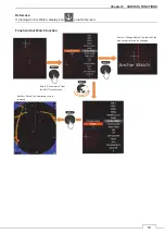
In the case of a fine weather, gain level is set close to the maximum
values usually. In the case of a bad weather, such as heavy rain or snow
or rough seas, it is necessary to adjust not only the gain level, but also
the sea clutter suppression function and rain/snow clutter suppression
function. You need to choose an appropriate level, respectively.
It is necessary to set an appropriate gain level in order to use the radar exactly.
Failure to do so, it is possible to obtain an accurate radar echo.
Examples of the radar echo sensitivity as follows.
Summary of Contents for JMA-3400 Series
Page 2: ......
Page 23: ...WARNING LABEL MOUNTING POINT xxi NKE 2103 4 4HS 6 6HS SCANNER UNIT NCD 2364 DISPLAY UNIT ...
Page 31: ...EQUIPMENT APPEARANCE xxix NKE 2043 SCANNER UNIT NKE 2063A AHS SCANNER UNIT ...
Page 32: ...EQUIPMENT APPEARANCE xxx NKE 2103 4 4HS 6 6HS SCANNER UNIT ...
Page 34: ...EQUIPMENT APPEARANCE xxxii Fuse ...
Page 48: ......
Page 51: ...Chapter 1 INSTALLATION 3 1 2 3 DIMENSIONAL DRAWING OF DISPLAY MOUNTING ...
Page 56: ...Chapter 1 INSTALLATION 8 FLUSH MOUNTING TEMPLATE Note Please note the paper size ...
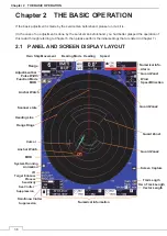
Page 85: ...Chapter 2 THE BASIC OPERATION 37 2 2 OPERATION UNIT ࢫࣆ ձ ղ ճ մ յ ն շ ո չ պ վ տ ւ ջ ռ ս ր ց ...
Page 266: ...Chapter 13 SPECIFICATIONS 218 13 1 SCANNER DIMENSION 13 1 1 NKE 2043 ...
Page 270: ...Chapter 13 SPECIFICATIONS 222 13 2 DISPLAY DIMENSION 13 2 1 NCD 2364 ...
Page 283: ...235 Chapter 13 SPECIFICATIONS MEMO ...
Page 293: ...APPENDIX A 10 MEMO ...
Page 313: ......