


Chapter 1 INSTALLATION
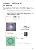
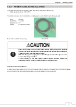
13
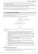
ELECTRICAL SELECTION CRITERIA
z
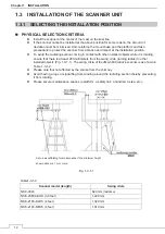
The installation height of the scanner relates to the maximum detection distance.
The higher, the better. However, if it is too high, radio wave energy greatly attenuates
above the scanner's vertical beam width (the point -3 dB from the peak of the main-lobe).
As a result, it is difficult to detect a close-in target. Sea clutter also increases.
Determine the installation height by taking into consideration the weight, maximum
length of the cable, and maintenance after installation. If the installation height of the
scanner is low, it is difficult to detect a long distance target. The ship's mast, derrick,
and chimney interfere with radiating beam causing the range that cannot be viewed
on the radar display to increase.
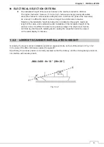
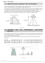
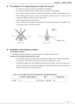
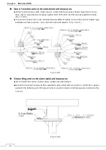
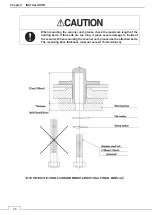
1.3.2 LOWEST SCANNER INSTALLATION HEIGHT
Generally, the lowest scanner installation position is supposed to be on the A-B line shown in Fig. 1-3-2.
In the case of the JMA-3400 series radar, 2
ș
equals 20°.
Specifically, the scanner position is normally elevated so that the chimney and the shrine-gate type mast do
not interfere with radiating beam.
JMA-3400 :
ș
= 10 ° (2
ș
= 20 °)
Fig. 1-3-2
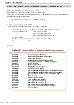
Summary of Contents for JMA-3400 Series
Page 2: ......
Page 23: ...WARNING LABEL MOUNTING POINT xxi NKE 2103 4 4HS 6 6HS SCANNER UNIT NCD 2364 DISPLAY UNIT ...
Page 31: ...EQUIPMENT APPEARANCE xxix NKE 2043 SCANNER UNIT NKE 2063A AHS SCANNER UNIT ...
Page 32: ...EQUIPMENT APPEARANCE xxx NKE 2103 4 4HS 6 6HS SCANNER UNIT ...
Page 34: ...EQUIPMENT APPEARANCE xxxii Fuse ...
Page 48: ......
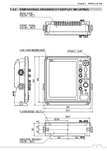
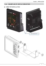
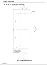
Page 51: ...Chapter 1 INSTALLATION 3 1 2 3 DIMENSIONAL DRAWING OF DISPLAY MOUNTING ...
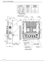
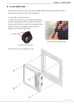
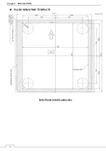
Page 56: ...Chapter 1 INSTALLATION 8 FLUSH MOUNTING TEMPLATE Note Please note the paper size ...
Page 85: ...Chapter 2 THE BASIC OPERATION 37 2 2 OPERATION UNIT ࢫࣆ ձ ղ ճ մ յ ն շ ո չ պ վ տ ւ ջ ռ ս ր ց ...
Page 266: ...Chapter 13 SPECIFICATIONS 218 13 1 SCANNER DIMENSION 13 1 1 NKE 2043 ...
Page 270: ...Chapter 13 SPECIFICATIONS 222 13 2 DISPLAY DIMENSION 13 2 1 NCD 2364 ...
Page 283: ...235 Chapter 13 SPECIFICATIONS MEMO ...
Page 293: ...APPENDIX A 10 MEMO ...
Page 313: ......