


197
Chapter 10 MAINTENANCE AND CHECK
[NKE-2063A/AHS, NKE-2103-4/4HS/6/6HS]
z
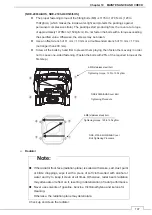
The proper fastening torque of the fitting bolts (M8) is 1176 to 1470 N•cm (120 to
150kgf•cm) (which makes the inside water-tight and protects the packings against
permanent compressive strain). The packings start producing from the cover at a torque
of approximately 1470N•cm (150kgf•cm). Do not fasten the bolts with a torque exceeding
the specified value. Otherwise, the screws may be broken.
z
Use an offset wrench of 11 mm × 13 mm or a double-ended wrench of 13 mm × 17 mm
(not longer than 200 mm).
z
Screw all the bolts by hand first to prevent them playing, then fasten them evenly in order
not to cause one-sided fastening. (Fasten the bolts with 25% of the required torque at the
first step.)
¾
Radiator
Note:
z
If the radiator front face (radiation plane) is soiled with smoke, salt, dust, paint
or birds’ droppings, wipe it with a piece of soft cloth wetted with alcohol or
water and try to keep it clean at all times. Otherwise, radar beam radiation
may attenuate or reflect on it, resulting in deterioration of radar performance.
z
Never use solvents of gasoline, benzine, trichloroethylene and ketone for
cleaning.
Otherwise, the radiation plane may deteriorate.
Check up and clean the radiator.
ձ
ղ
ճ
մ
մ
ճ
ղ
ձ
NKE-2103-4/4HS/6/6HS Cover
Bolt Tightening Procedure
4-M8 (stainless steel) bolt
Tightening torque: 120 to 150 kgf/cm
NKE-2063A/AHS Cover Bolt
Tightening Procedure
4-M8 (stainless steel) bolt
Tightening torque: 120 to 150 kgf/cm
Summary of Contents for JMA-3400 Series
Page 2: ......
Page 23: ...WARNING LABEL MOUNTING POINT xxi NKE 2103 4 4HS 6 6HS SCANNER UNIT NCD 2364 DISPLAY UNIT ...
Page 31: ...EQUIPMENT APPEARANCE xxix NKE 2043 SCANNER UNIT NKE 2063A AHS SCANNER UNIT ...
Page 32: ...EQUIPMENT APPEARANCE xxx NKE 2103 4 4HS 6 6HS SCANNER UNIT ...
Page 34: ...EQUIPMENT APPEARANCE xxxii Fuse ...
Page 48: ......
Page 51: ...Chapter 1 INSTALLATION 3 1 2 3 DIMENSIONAL DRAWING OF DISPLAY MOUNTING ...
Page 56: ...Chapter 1 INSTALLATION 8 FLUSH MOUNTING TEMPLATE Note Please note the paper size ...
Page 85: ...Chapter 2 THE BASIC OPERATION 37 2 2 OPERATION UNIT ࢫࣆ ձ ղ ճ մ յ ն շ ո չ պ վ տ ւ ջ ռ ս ր ց ...
Page 266: ...Chapter 13 SPECIFICATIONS 218 13 1 SCANNER DIMENSION 13 1 1 NKE 2043 ...
Page 270: ...Chapter 13 SPECIFICATIONS 222 13 2 DISPLAY DIMENSION 13 2 1 NCD 2364 ...
Page 283: ...235 Chapter 13 SPECIFICATIONS MEMO ...
Page 293: ...APPENDIX A 10 MEMO ...
Page 313: ......