

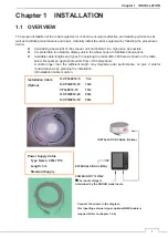


Chapter 1 INSTALLATION
7
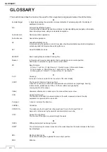
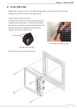
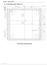
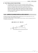
FLUSH MOUNTING
Remove base, and take out cover of front panel. Please slide out, when removing of the front caps.
And refer to how to side out of the front caps below as.
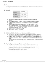
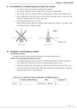
/// How to slide out of the front cap ///
The back of the front cap has two flat ends as below figure.
Using two index fingers, push up on these two flat sides at
the same time. At this time, support the front panel with both
thumbs as shown in the right figure, but be careful not
support by your thumb on the front cap.
Fix with the front 4 corner screws to the wall.
Two flat ends
The back of the front cap
How to slide out of the front cap
Summary of Contents for JMA-3400 Series
Page 2: ......
Page 23: ...WARNING LABEL MOUNTING POINT xxi NKE 2103 4 4HS 6 6HS SCANNER UNIT NCD 2364 DISPLAY UNIT ...
Page 31: ...EQUIPMENT APPEARANCE xxix NKE 2043 SCANNER UNIT NKE 2063A AHS SCANNER UNIT ...
Page 32: ...EQUIPMENT APPEARANCE xxx NKE 2103 4 4HS 6 6HS SCANNER UNIT ...
Page 34: ...EQUIPMENT APPEARANCE xxxii Fuse ...
Page 48: ......
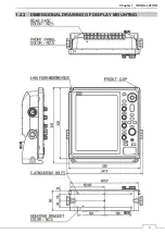
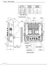
Page 51: ...Chapter 1 INSTALLATION 3 1 2 3 DIMENSIONAL DRAWING OF DISPLAY MOUNTING ...
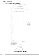
Page 56: ...Chapter 1 INSTALLATION 8 FLUSH MOUNTING TEMPLATE Note Please note the paper size ...
Page 85: ...Chapter 2 THE BASIC OPERATION 37 2 2 OPERATION UNIT ࢫࣆ ձ ղ ճ մ յ ն շ ո չ պ վ տ ւ ջ ռ ս ր ց ...
Page 266: ...Chapter 13 SPECIFICATIONS 218 13 1 SCANNER DIMENSION 13 1 1 NKE 2043 ...
Page 270: ...Chapter 13 SPECIFICATIONS 222 13 2 DISPLAY DIMENSION 13 2 1 NCD 2364 ...
Page 283: ...235 Chapter 13 SPECIFICATIONS MEMO ...
Page 293: ...APPENDIX A 10 MEMO ...
Page 313: ......