


Chapter 13 SPECIFICATIONS
224
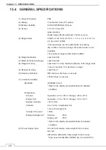
13.4 GENERAL SPECIFICATIONS
(1) Class of Emission
P0N
(2) Display
Color Raster Scan, PPI system
(3)Display capability
SVGA (800x600dots) Screen
(4) Screen
12.1-inch Color LCD
Glass
bonding
Radar image effective diameter 150mm or more.
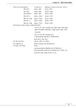
(5) Range Scale
0.0625, 0.125, 0.25, 0.5, 0.75, 1, 1.5, 2, 3, 4, 6, 8, 12, 16,
24, 32, 48, 64, 72NM
*The used range can be disabled with user setting.
(64, 72 NM or maximum range: off-center function is not
available.
The maximum range of JMA-3404 is 48NM.)
(6) Range Resolution
Less than 30m
(7) Minimum Detective Range
Less than 40m
(8) Range Accuracy
Less than 1% of the maximum distance of the range scale
in use or less than 15m whichever is larger.
(9) Bearing Accuracy
Less than ±1°
(10) Bearing Indication
RM: Head-up, North-up, Course-up
TM: North-up, Course-up
(11) Ambient Condition
Standards IEC60945
Ed.4.0
* Refer to the display unit specifications for detailed
conditions.
Temperature:
Scanner
Operation: -25 to +55°C / Storage: -25 to +70°C
Display Unit
Operation: -15 to +55°C / Storage: -15 to +70°C
Relative Humidity
+40°C, 93%
Vibration
2 to 13.2 Hz, amplitude±1mm
13.2 to 100 Hz @0.7 G
Velocity of the wind
100kn
Waterproof/dustproof Scanner
IP26
Display unit
IP55
* Refer to the display unit specifications for detailed
conditions.
(12) Power Supply Input
DC+24V (All models, cable length of 30m or less)
DC+12V
(JMA-3404, JMA-3406, cable length of 20m or less.
*High speed model JMA-3406HS can not use DC12V.)
Summary of Contents for JMA-3400 Series
Page 2: ......
Page 23: ...WARNING LABEL MOUNTING POINT xxi NKE 2103 4 4HS 6 6HS SCANNER UNIT NCD 2364 DISPLAY UNIT ...
Page 31: ...EQUIPMENT APPEARANCE xxix NKE 2043 SCANNER UNIT NKE 2063A AHS SCANNER UNIT ...
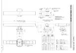
Page 32: ...EQUIPMENT APPEARANCE xxx NKE 2103 4 4HS 6 6HS SCANNER UNIT ...
Page 34: ...EQUIPMENT APPEARANCE xxxii Fuse ...
Page 48: ......
Page 51: ...Chapter 1 INSTALLATION 3 1 2 3 DIMENSIONAL DRAWING OF DISPLAY MOUNTING ...
Page 56: ...Chapter 1 INSTALLATION 8 FLUSH MOUNTING TEMPLATE Note Please note the paper size ...
Page 85: ...Chapter 2 THE BASIC OPERATION 37 2 2 OPERATION UNIT ࢫࣆ ձ ղ ճ մ յ ն շ ո չ պ վ տ ւ ջ ռ ս ր ց ...
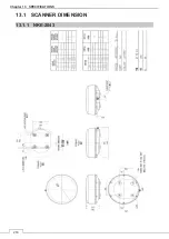
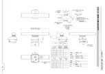
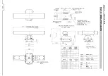
Page 266: ...Chapter 13 SPECIFICATIONS 218 13 1 SCANNER DIMENSION 13 1 1 NKE 2043 ...
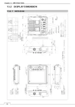
Page 270: ...Chapter 13 SPECIFICATIONS 222 13 2 DISPLAY DIMENSION 13 2 1 NCD 2364 ...
Page 283: ...235 Chapter 13 SPECIFICATIONS MEMO ...
Page 293: ...APPENDIX A 10 MEMO ...
Page 313: ......