


199
Chapter 10 MAINTENANCE AND CHECK
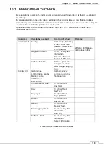
10.3 PERFORMANCE CHECK
Make operational check on the radar equipment regularly and if any problem is found, investigate it
immediately.
Pay special attention to the high voltage sections in checking and take full care that no trouble is
caused by any error or carelessness in measurement. Please take note of the results of checking, the
reason can be used effectively in the next check work.
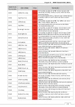
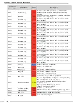
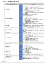
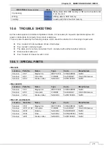
Operational check shall be made in accordance with Table 10.3.1 Performance Check List in
the order as specified in it.
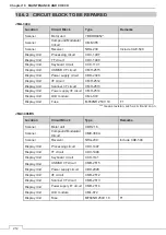
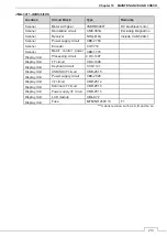
Equipment
Item to be checked
Criteria or Method
Remarks
Scanner Unit
Tuning
Can be adjusted tuning
at the manual tune.
Observe a weak echo
as far possible.
24NM or 48NM range
during transmitting
Magnetron Current
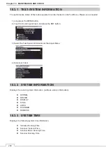
10.3.1 Test-System
Information
Scanner information
The bar is 50% more
Antenna Rotation
Rotation speed can
change slow, when
small Range changing
to up.
Display Unit
Gain can be
LCD brilliance can be
Marker can be
VRM can be
EBL can be
Can be correctly
controlled using the
functional icon.
Communication Lines
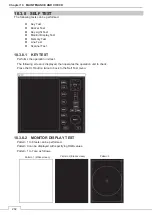
10.3.8 Self Test
Line Test
Key
10.3.8 Self Test
Key Test
Key Light
10.3.8 Self Test
Key Light Test
Buzzer
10.3.8 Self Test
Buzzer Test
Memory
10.3.8 Self Test
Memory Test
Error Logging check
10.3.1 Test-System
Information
Error Log
Software check
10.3.1 Test-System
Information
System Information
Table 10.3.1 Performance Check List
Summary of Contents for JMA-3400 Series
Page 2: ......
Page 23: ...WARNING LABEL MOUNTING POINT xxi NKE 2103 4 4HS 6 6HS SCANNER UNIT NCD 2364 DISPLAY UNIT ...
Page 31: ...EQUIPMENT APPEARANCE xxix NKE 2043 SCANNER UNIT NKE 2063A AHS SCANNER UNIT ...
Page 32: ...EQUIPMENT APPEARANCE xxx NKE 2103 4 4HS 6 6HS SCANNER UNIT ...
Page 34: ...EQUIPMENT APPEARANCE xxxii Fuse ...
Page 48: ......
Page 51: ...Chapter 1 INSTALLATION 3 1 2 3 DIMENSIONAL DRAWING OF DISPLAY MOUNTING ...
Page 56: ...Chapter 1 INSTALLATION 8 FLUSH MOUNTING TEMPLATE Note Please note the paper size ...
Page 85: ...Chapter 2 THE BASIC OPERATION 37 2 2 OPERATION UNIT ࢫࣆ ձ ղ ճ մ յ ն շ ո չ պ վ տ ւ ջ ռ ս ր ց ...
Page 266: ...Chapter 13 SPECIFICATIONS 218 13 1 SCANNER DIMENSION 13 1 1 NKE 2043 ...
Page 270: ...Chapter 13 SPECIFICATIONS 222 13 2 DISPLAY DIMENSION 13 2 1 NCD 2364 ...
Page 283: ...235 Chapter 13 SPECIFICATIONS MEMO ...
Page 293: ...APPENDIX A 10 MEMO ...
Page 313: ......