


Chapter 5 VARIOUS FUNCTIONS
94
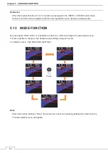
Head Up (H-UP) mode is displayed so that the ship’s heading line points to the zenith of the PPI. Since
targets are displayed in their direction relative to the ship’s heading line, the operator can view the video in the
same field of view as in operating the ship at sea. This mode is suitable for watching over other ships.
North Up (N-UP) mode is displayed so that the zenith of the PPI points to the due north. Fixed targets do no
flicker and are easily identified on the chart, and the true bearing of a target can easily be read out.
Course Up (C-UP) mode is fixed pointing to the zenith of the PPI points to the due north. In the same way as
in the N-UP mode, fixed targets do not flicker, and are stabilized even if the ship is yawing. The bearing of the
heading line varies by the same shift of own ship’s course. If the course is changed while “Course Up” is
selected, the latest course will be displayed top of the radar screen by selecting “Course Up Reset.”
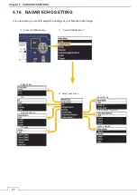
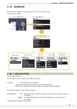
5.20 TRAILS SETTING
Set radar trails.
䐡
Select each menu.
㻌
䐟
Press the MENU button.
㻌
䐠
Select
“Trails.”
㻌
Threshold
Time/All Combine
Trails Mode
To 5.20.1
㻌
To 5.20.2
㻌
To 5.20.3
㻌
Summary of Contents for JMA-3400 Series
Page 2: ......
Page 23: ...WARNING LABEL MOUNTING POINT xxi NKE 2103 4 4HS 6 6HS SCANNER UNIT NCD 2364 DISPLAY UNIT ...
Page 31: ...EQUIPMENT APPEARANCE xxix NKE 2043 SCANNER UNIT NKE 2063A AHS SCANNER UNIT ...
Page 32: ...EQUIPMENT APPEARANCE xxx NKE 2103 4 4HS 6 6HS SCANNER UNIT ...
Page 34: ...EQUIPMENT APPEARANCE xxxii Fuse ...
Page 48: ......
Page 51: ...Chapter 1 INSTALLATION 3 1 2 3 DIMENSIONAL DRAWING OF DISPLAY MOUNTING ...
Page 56: ...Chapter 1 INSTALLATION 8 FLUSH MOUNTING TEMPLATE Note Please note the paper size ...
Page 85: ...Chapter 2 THE BASIC OPERATION 37 2 2 OPERATION UNIT ࢫࣆ ձ ղ ճ մ յ ն շ ո չ պ վ տ ւ ջ ռ ս ր ց ...
Page 266: ...Chapter 13 SPECIFICATIONS 218 13 1 SCANNER DIMENSION 13 1 1 NKE 2043 ...
Page 270: ...Chapter 13 SPECIFICATIONS 222 13 2 DISPLAY DIMENSION 13 2 1 NCD 2364 ...
Page 283: ...235 Chapter 13 SPECIFICATIONS MEMO ...
Page 293: ...APPENDIX A 10 MEMO ...
Page 313: ......