


Chapter 5 VARIOUS FUNCTIONS
95
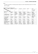
5.20.1 THRESHOLD
Set the threshold level for making radar trails.
The threshold is higher in the order of level 1 < level 2 < level 3 < level 4.
If the threshold is low, radar trails are plotted even for weak echoes.
If the threshold is high, radar trails are only plotted for strong echoes.
z
When radar trails are plotted with unwanted waves, change to a higher level.
z
To thin radar trails, change to a higher level.
z
If radar trails are plotted in snatches, change to a lower level.
5.20.2 TIME/ALL COMBINE
This function superimpose-displays time radar trails and continuous radar trails.
Normally, time radar trails have priority, but if continuous radar trail is selected in the MULTI control menu,
only continuous radar trails is displayed.
5.20.3 TRAILS MODE
Switch the radar trail display between true and relative motion trail modes.
True motion trails: The system plots the absolute motion trails of a target, irrespective of own ship’s
position.
The operator can easily judge the course and speed of the target.
The system does not plot the trails of land and other fixed targets.
Relative motion trails: The system plots the trails of a target at a position relative to the own ship.
The operator can easily judge whether the target is approaching the own ship.
While the own ship is moving, the system also plots the trails when the own ship is
turning.
Summary of Contents for JMA-3400 Series
Page 2: ......
Page 23: ...WARNING LABEL MOUNTING POINT xxi NKE 2103 4 4HS 6 6HS SCANNER UNIT NCD 2364 DISPLAY UNIT ...
Page 31: ...EQUIPMENT APPEARANCE xxix NKE 2043 SCANNER UNIT NKE 2063A AHS SCANNER UNIT ...
Page 32: ...EQUIPMENT APPEARANCE xxx NKE 2103 4 4HS 6 6HS SCANNER UNIT ...
Page 34: ...EQUIPMENT APPEARANCE xxxii Fuse ...
Page 48: ......
Page 51: ...Chapter 1 INSTALLATION 3 1 2 3 DIMENSIONAL DRAWING OF DISPLAY MOUNTING ...
Page 56: ...Chapter 1 INSTALLATION 8 FLUSH MOUNTING TEMPLATE Note Please note the paper size ...
Page 85: ...Chapter 2 THE BASIC OPERATION 37 2 2 OPERATION UNIT ࢫࣆ ձ ղ ճ մ յ ն շ ո չ պ վ տ ւ ջ ռ ս ր ց ...
Page 266: ...Chapter 13 SPECIFICATIONS 218 13 1 SCANNER DIMENSION 13 1 1 NKE 2043 ...
Page 270: ...Chapter 13 SPECIFICATIONS 222 13 2 DISPLAY DIMENSION 13 2 1 NCD 2364 ...
Page 283: ...235 Chapter 13 SPECIFICATIONS MEMO ...
Page 293: ...APPENDIX A 10 MEMO ...
Page 313: ......