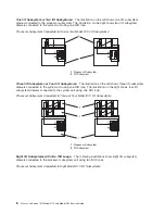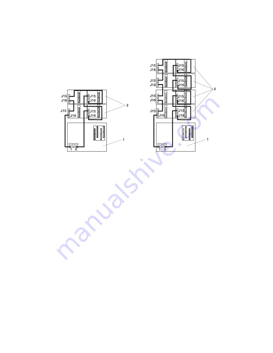
Four
I/O
Subsystems,
Eight
I/O
Subsystems:
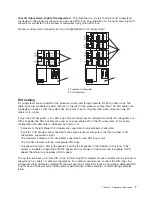
The
illustration
on
the
left
shows
four
I/O
subsystems
connected
to
the
processor
subsystem
using
one
SPCN
loop.
The
illustration
on
the
right
shows
eight
I/O
subsystems
connected
to
the
processor
subsystem
using
one
SPCN
loop.
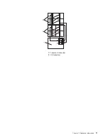
Processor
Subsystem
Connected
to
Four
or
Eight
Model
D10
I/O
Subsystems:
1
Processor
Subsystem
2
I/O
Subsystem
RIO
Cabling
I/O
subsystems
are
connected
to
the
processor
subsystem
through
remote
I/O
(RIO)
cable
loops.
The
cable
loops
are
connected
to
ports
that
are
on
the
rear
of
the
processor
subsystem.
The
RIO
cables
are
connected
in
loops
so
that
the
system
has
two
paths
to
each
I/O
subsystem
when
more
than
one
I/O
drawer
is
in
a
loop.
If
only
one
I/O
subsystem
is
in
a
RIO
loop
and
both
the
processor
subsystem
and
the
I/O
subsystem
are
RIO-2
capable,
the
RIO-2
cables
are
used
as
one
two-cable
path
to
the
I/O
subsystem.
In
this
cable
configuration,
the
data
rate
is
increased
by
a
factor
of
2.
v
A
maximum
of
eight
Model
D10
drawers
are
supported
on
one
processor
subsystem.
v
If
both
D10
I/O
drawers
are
connected
to
the
same
processor
subsystem,
the
total
number
of
I/O
subsystems
supported
is
eight.
v
The
maximum
number
of
I/O
subsystems
supported
on
one
RIO
loop
is
four.
v
The
D10
I/O
drawers
must
be
on
separate
RIO
loops.
v
The
speed
at
which
a
RIO
loop
operates
is
set
by
the
capability
of
the
drawers
on
the
loop.
If
the
system
is
capable
of
operating
at
RIO-2
speed,
but
any
drawer
on
the
same
loop
is
capable
of
RIO
speed,
the
whole
loop
operates
at
RIO
speed.
The
system
can
have
up
to
four
RIO
loops.
A
total
of
eight
I/O
drawers
can
be
connected
to
the
processor
subsystem
in
a
variety
of
cabling
configurations.
For
optimum
performance,
connect
the
RIO
loops
in
a
configuration
that
distributes
multiple
I/O
drawers
among
as
many
RIO
loops
as
possible.
A
dedicated
RIO
loop
for
each
I/O
drawer
can
provide
optimum
performance.
Some
examples
of
valid
cabling
examples
follow.
Chapter
1.
Reference
Information
7
Summary of Contents for eserver pSeries 7311 D10
Page 1: ...pSeries 7311 Model D10 and Model D20 Service Guide SA38 0627 01 ERserver...
Page 2: ......
Page 3: ...pSeries 7311 Model D10 and Model D20 Service Guide SA38 0627 01 ERserver...
Page 8: ...vi Eserver pSeries 7311 Model D10 and Model D20 Service Guide...
Page 12: ...x Eserver pSeries 7311 Model D10 and Model D20 Service Guide...
Page 14: ...xii Eserver pSeries 7311 Model D10 and Model D20 Service Guide...
Page 25: ...1 Processor Subsystem 2 I O Subsystem Chapter 1 Reference Information 9...
Page 89: ...Chapter 3 Removal and Replacement Procedures 73...
Page 99: ...2 1 1 Top of Cassette 2 Handle Chapter 3 Removal and Replacement Procedures 83...
Page 179: ...D10 I O Subsystem Parts continued 1 2 3 4 5 6 7 Chapter 4 Parts Information 163...
Page 207: ......

