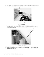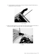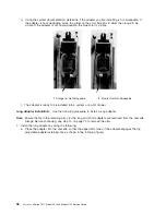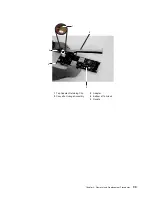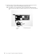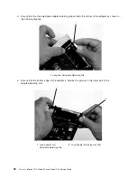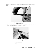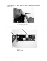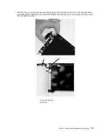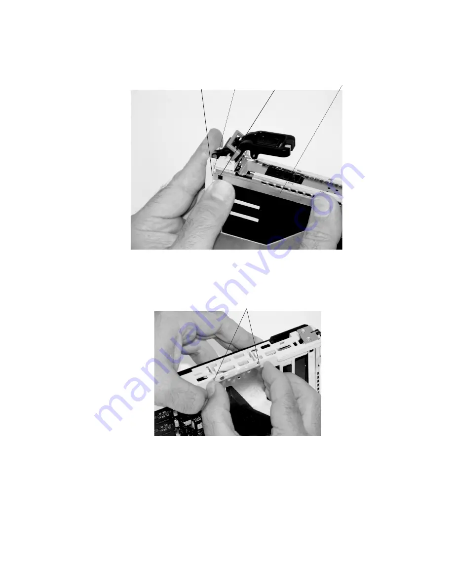
3)
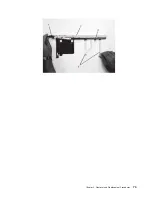
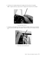
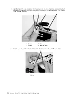
Align
the
top
of
the
bezel
assembly
into
the
grooves
on
the
top
of
the
cassette
assembly.
Push
the
bezel
onto
the
cassette
linkage
until
the
tab
on
the
top
of
the
bezel
is
seated
in
the
recess
of
the
cassette
assembly.
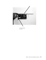
1
2
3
4
1
Recess
3
Tab
2
Groove
4
Bezel
Assembly
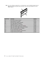
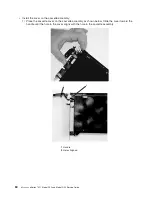
4)
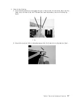
Insert
the
two
tabs
on
the
bezel
extension
into
the
two
slots
on
the
cassette
assembly.
1
1
Tabs
86
Eserver
pSeries
7311
Model
D10
and
Model
D20
Service
Guide
Summary of Contents for eserver pSeries 7311 D10
Page 1: ...pSeries 7311 Model D10 and Model D20 Service Guide SA38 0627 01 ERserver...
Page 2: ......
Page 3: ...pSeries 7311 Model D10 and Model D20 Service Guide SA38 0627 01 ERserver...
Page 8: ...vi Eserver pSeries 7311 Model D10 and Model D20 Service Guide...
Page 12: ...x Eserver pSeries 7311 Model D10 and Model D20 Service Guide...
Page 14: ...xii Eserver pSeries 7311 Model D10 and Model D20 Service Guide...
Page 25: ...1 Processor Subsystem 2 I O Subsystem Chapter 1 Reference Information 9...
Page 89: ...Chapter 3 Removal and Replacement Procedures 73...
Page 99: ...2 1 1 Top of Cassette 2 Handle Chapter 3 Removal and Replacement Procedures 83...
Page 179: ...D10 I O Subsystem Parts continued 1 2 3 4 5 6 7 Chapter 4 Parts Information 163...
Page 207: ......


