D20
Service
Position
Attention:
When
placing
your
Model
D20
subsystem
into
the
service
position,
all
stability
plates
must
be
firmly
in
position
to
prevent
the
rack
from
toppling.
Ensure
that
only
one
system
drawer
is
in
the
service
position
at
a
time.
Before
doing
any
service
actions
inside
your
Model
D20
subsystem,
put
the
Model
D20
subsystem
into
the
service
position.
To
place
the
drawer
into
the
service
position,
do
the
following:
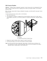
1.
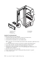
Open
the
front
rack
door.
2.
If
your
Model
D20
subsystem
is
equipped
with
two
blue
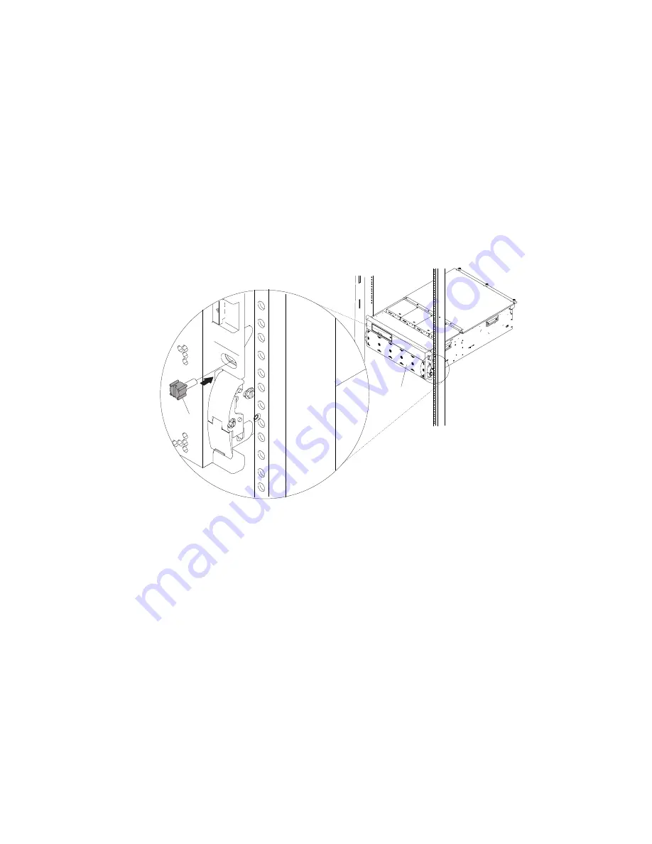
thumbscrews
securing
it
to
the
rack,
remove
the
thumbscrews
at
this
time.
The
screws
are
located
on
the
bezel,
just
above
each
subsystem
release
latch.
2
1
1
Front
Bezel
2
Transport
Retaining
Screw
for
System
Drawer
3.
Release
the
subsystem
release
latches
located
on
the
left
and
right
side.
4.
Pull
the
system
drawer
out
from
the
rack
until
the
rails
are
fully
extended.
Note:
When
the
system
rails
are
fully
extended,
safety
latches
on
the
slide
rails
lock
into
place.
This
action
prevents
the
system
from
being
accidentally
pulled
out
too
far
and
dropped.
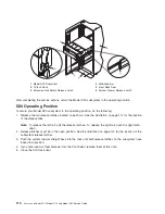
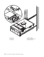
The
following
illustration
shows
a
system
drawer
in
the
service
position.
Chapter
3.
Removal
and
Replacement
Procedures
113
Summary of Contents for eserver pSeries 7311 D10
Page 1: ...pSeries 7311 Model D10 and Model D20 Service Guide SA38 0627 01 ERserver...
Page 2: ......
Page 3: ...pSeries 7311 Model D10 and Model D20 Service Guide SA38 0627 01 ERserver...
Page 8: ...vi Eserver pSeries 7311 Model D10 and Model D20 Service Guide...
Page 12: ...x Eserver pSeries 7311 Model D10 and Model D20 Service Guide...
Page 14: ...xii Eserver pSeries 7311 Model D10 and Model D20 Service Guide...
Page 25: ...1 Processor Subsystem 2 I O Subsystem Chapter 1 Reference Information 9...
Page 89: ...Chapter 3 Removal and Replacement Procedures 73...
Page 99: ...2 1 1 Top of Cassette 2 Handle Chapter 3 Removal and Replacement Procedures 83...
Page 179: ...D10 I O Subsystem Parts continued 1 2 3 4 5 6 7 Chapter 4 Parts Information 163...
Page 207: ......

