Long
Adapter
Removal:
To
remove
a
long
adapter,
do
the
following:
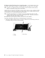
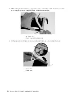
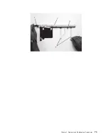
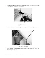
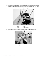
1.
Each
adapter
arm
has
a
release
tab
that
allows
the
arm
to
be
moved
away
from
the
adapter
in
the
cassette
assembly.
Use
your
fingernail
to
lift
the
tab,
to
allow
the
arm
to
be
moved
away
from
the
adapter.
Lift
the
release
tab
on
the
long
adapter
arm,
and
slide
it
off
the
cassette
linkage
assembly.
1
Release
Tab
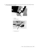
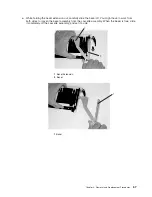
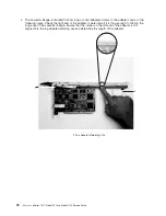
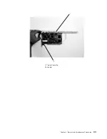
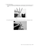
2.
Remove
the
adapter
from
the
cassette
linkage
assembly
by
rotating
the
bottom
of
the
tailstock
out,
as
shown
in
the
following
illustration.
Store
the
adapter
in
a
safe
place.
1
Cassette
Linkage
Assembly
3
Bottom
of
Tailstock
2
Adapter
4
Handle
3.
The
removal
procedure
for
the
PCI
adapter
cassette
assembly
is
complete.
To
install
a
new
adapter
or
blank
filler
in
the
cassette,
go
to
“Installing
a
Hot-Pluggable
PCI
Adapter”
on
page
57.
Replacing
an
Adapter
in
a
PCI
Adapter
Cassette:
This
procedure
is
performed
when
preparing
to
install
a
new
adapter
or
a
blank
filler
in
the
processor
subsystem
or
an
I/O
drawer.
Familiarize
yourself
with
the
entire
procedure
before
performing
the
following
steps.
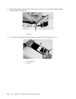
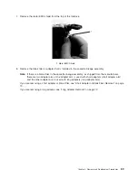
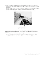
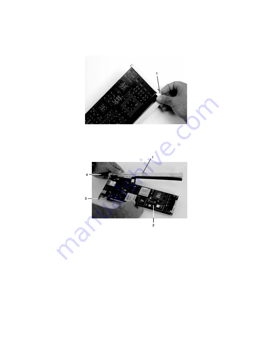
1.
Place
the
empty
PCI
adapter
cassette
linkage
on
a
flat
work
surface
in
front
of
you.
Position
the
cassette
so
that
the
handle
is
in
the
raised
(up
position),
and
on
the
left,
with
the
top
of
the
linkage
facing
away
from
you.
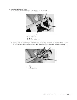
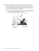
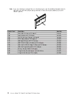
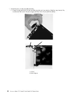
Note:
Your
PCI
adapter
cassette
linkage
might
not
have
the
short
or
long
adapter
retaining
arms
installed
if
you
removed
them
during
the
remove
procedure.
In
the
following
figure,
both
arms
are
shown.
72
Eserver
pSeries
7311
Model
D10
and
Model
D20
Service
Guide
Summary of Contents for eserver pSeries 7311 D10
Page 1: ...pSeries 7311 Model D10 and Model D20 Service Guide SA38 0627 01 ERserver...
Page 2: ......
Page 3: ...pSeries 7311 Model D10 and Model D20 Service Guide SA38 0627 01 ERserver...
Page 8: ...vi Eserver pSeries 7311 Model D10 and Model D20 Service Guide...
Page 12: ...x Eserver pSeries 7311 Model D10 and Model D20 Service Guide...
Page 14: ...xii Eserver pSeries 7311 Model D10 and Model D20 Service Guide...
Page 25: ...1 Processor Subsystem 2 I O Subsystem Chapter 1 Reference Information 9...
Page 89: ...Chapter 3 Removal and Replacement Procedures 73...
Page 99: ...2 1 1 Top of Cassette 2 Handle Chapter 3 Removal and Replacement Procedures 83...
Page 179: ...D10 I O Subsystem Parts continued 1 2 3 4 5 6 7 Chapter 4 Parts Information 163...
Page 207: ......

