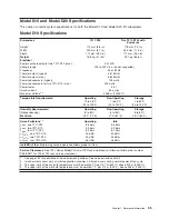
Model
D20
Specifications
Dimensions
Height
178
mm
(7.0
in)
Width
445
mm
(17.5
in)
Depth
610
mm
(24.0
in)
Maximum
Weight
45.9kg
(101
lbs)
Electrical
Power
source
loading
(max.)
0.358
kVA
Voltage
range
100
to
240
V
ac,
V
dc
not
supported
Frequency
50
or
60
Hz
Thermal
output
(typical)
774
Btu/hr
Thermal
output
(max.)
1161
Btu/hr
Power
requirements
(typical)
227
watts
Power
requirements
for
two
7311-D20
(max.)
340
watts
Power
factor
0.91
Inrush
current
²
60
amps
Maximum
altitude
3,
4
3048
m
(10,000
ft.)
Temperature
Requirements
³
Operating
5
to
35°C
41
to
95°F)
Non-Operating
1
to
43°C
(34
to
109°F)
Storage
1
to
60°C
(34
to
140°F)
Humidity
Requirements
⁴
Operating
Non-Operating
Storage
(Noncondensing)
8
to
80%
8
to
80%
5
to
80%
Wet
Bulb
23°C
(73°F)
27°C
(81°F)
29°C
(84°F)
Noise
Emissions
1,
5
Operating
Idle
L
WAd
6.1
bels
6.0
bels
<L
pA
>
m
44
dBA
43
dBA
Install/Air
Flow
Maintaining
service
clearance
allows
proper
air
flow.
Service
Clearances
:
See
7014
Series
Model
T00
and
T42
Rack
Installation
and
Service
Guide
,
order
number
SA38-0577
for
T00
or
T42
rack
service
clearances.
1.
See
182
for
definitions
of
noise
emissions
positions.
See
noise
emissions
note
4.
2.
Inrush
currents
occur
only
at
initial
application
of
power,
no
inrush
occurs
during
normal
power
off-on
cycle.
3.
The
upper
limit
of
the
dry
bulb
temperature
must
be
derated
1
degree
C
per
137
m
(450
ft.)
above
915
m
(3000
ft.).
4.
The
upper
limit
of
the
wet
bulb
temperature
must
be
derated
1
degree
C
per
274
m
(900
ft.
)
above
305
m
(1000
ft.).
36
Eserver
pSeries
7311
Model
D10
and
Model
D20
Service
Guide
Summary of Contents for eserver pSeries 7311 D10
Page 1: ...pSeries 7311 Model D10 and Model D20 Service Guide SA38 0627 01 ERserver...
Page 2: ......
Page 3: ...pSeries 7311 Model D10 and Model D20 Service Guide SA38 0627 01 ERserver...
Page 8: ...vi Eserver pSeries 7311 Model D10 and Model D20 Service Guide...
Page 12: ...x Eserver pSeries 7311 Model D10 and Model D20 Service Guide...
Page 14: ...xii Eserver pSeries 7311 Model D10 and Model D20 Service Guide...
Page 25: ...1 Processor Subsystem 2 I O Subsystem Chapter 1 Reference Information 9...
Page 89: ...Chapter 3 Removal and Replacement Procedures 73...
Page 99: ...2 1 1 Top of Cassette 2 Handle Chapter 3 Removal and Replacement Procedures 83...
Page 179: ...D10 I O Subsystem Parts continued 1 2 3 4 5 6 7 Chapter 4 Parts Information 163...
Page 207: ......

