background image

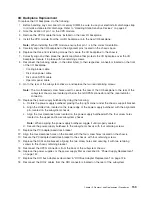
I/O


Backplane


Replacement


To


replace


the


I/O


backplane,


do


the


following:


1.


Before


handling


any


card,


board,


or


memory


DIMM,


be


sure


to


use


your


electrostatic


discharge


strap


to


minimize


static-electric


discharge.


Refer


to


“Handling


Static-Sensitive


Devices”


on


page


42.


2.


Note


the


location


of


pin


1


on


the


VPD


module.


3.


Remove


the


VPD


module


that


was


installed


on


the


new


I/O


backplane.


4.


Install


the


VPD


module


from


the


old


I/O


backplane


onto


the


new


I/O


backplane.

Note:


When


installing


the


VPD


module,


ensure


that


pin


1


is


in


the


correct


orientation.


5.


Carefully


align


the


I/O


backplane


to


the


alignment


pins


located


on


the


chassis


base.


6.


Replace


the


three


front


retaining


screws


that


secure


the


I/O


backplane


to


the


chassis.


7.


Correctly


align


and


then


place


the


plastic


membrane


that


protects


the


I/O


backplane


over


the


I/O


backplane.


Secure


it


in


place


with


five


retaining


screws.


8.


Reconnect


the


following


cables,


in


the


order


listed,


to


their


respective


connectors


located


on


the


front


of


the


I/O


backplane:


v


Cooling


blower


cable


v


Disk


drive


power


cable


v


Disk


drive


SPCN


cable


v


Operator


panel


cable


9.


Go


to


the


rear


of


the


subsystem


chassis,


and


replace


the


two


rear


retaining


screws.

Note:


The


two


threaded


screw


holes


used


to


secure


the


rear


of


the


I/O


backplane


to


the


rear


of


the


subsystem


chassis


are


located


just


below


the


left


SPCN


connector


and


the


rack-indicator


connector.


10.


Replace


the


power-supply


bulkhead


by


doing


the


following:


a.


Rotate


the


power-supply


bulkhead,


placing


the


top


right


corner


under


the


chassis


support


bracket.


b.


Align


the


slotted


tab,


located


on


the


lower


edge


of


the


power


supply


bulkhead,


with


the


alignment


pin,


located


on


the


subsystem


chassis.


c.


Align


the


four


clearance


holes


located


on


the


power-supply


bulkhead


with


the


four


screw


holes


located


on


the


upper


and


lower


subsystem


chassis.

Note:


When


aligning


the


power-supply


bulkhead,


wiggle


it


until


properly


seated.


d.


Secure


the


power-supply


bulkhead


to


the


subsystem


chassis


with


four


retaining


screws.

11.


Replace


the


PCI


adapter-headstock


bracket.


12.


Align


the


four


clearance


holes


on


the


bracket


with


the


four


screw


holes


located


on


the


chassis.


13.


Secure


the


PCI


adapter-headstock


bracket


to


the


chassis


with


four


retaining


screws.


14.


Replace


the


SCSI


cable


bracket,


aligning


the


two


screw


holes


and


securing


it


with


two


retaining


screws


to


the


chassis


retaining


bracket.


15.


Reconnect


the


SPCN


connectors


from


the


back


of


the


subsystem


chassis.


16.


Replace


the


power


supplies


or


the


power


supply


filler


as


described


in


“Power


Supply


Replacement”


on


page


151.


17.


Replace


the


RIO


bus


adapter


as


described


in


“RIO


Bus


Adapter


Replacement”


on


page


126.


18.


Reconnect


the


RIO-2


cables


from


the


RIO


connectors


located


on


the


rear


of


the


subsystem.


Chapter


3.


Removal


and


Replacement


Procedures


159

Summary of Contents for eserver pSeries 7311 D10

Page 1: ...pSeries 7311 Model D10 and Model D20 Service Guide SA38 0627 01 ERserver...

Page 2: ......

Page 3: ...pSeries 7311 Model D10 and Model D20 Service Guide SA38 0627 01 ERserver...

Page 4: ...to Information Development Department H6DS 905 6C006 11501 Burnet Road Austin Texas 78758 3493 To send comments electronically use this commercial internet address aix6kpub austin ibm com Any informat...

Page 5: ...I O Subsystem Rear Locations 11 Model D10 I O Backplane Locations 12 Model D10 I O Subsystem PHB 13 Model D10 Location Codes 14 AIX and Physical Location Code Table 14 7311 Model D10 I O Subsystem Lo...

Page 6: ...14 D20 Service Access Cover 115 D20 Front Bezel 116 D20 Operator Panel 117 D20 Blowers 119 D20 Cooling Blower Cable 122 D20 RIO Bus Adapter Assembly 124 D20 PCI Adapters 127 D20 Hot Plug Disk Drives 1...

Page 7: ...Disposal 177 Environmental Design 181 Acoustical Noise Emissions 182 pSeries 7311 Model D10 Declared Acoustical Noise Emissions 182 pSeries 7311 Model D20 Declared Acoustical Noise Emissions 182 Appen...

Page 8: ...vi Eserver pSeries 7311 Model D10 and Model D20 Service Guide...

Page 9: ...gh the unit must not be in direct contact with the rack v Care should be taken to ensure that a hazardous condition is not created due to uneven mechanical loading when installing this unit in a rack...

Page 10: ...ables ensure that the power cables for the system unit and all attached devices are unplugged When adding or removing any additional devices to or from the system ensure that the power cables for thos...

Page 11: ...laser certification numbers and approval information CAUTION All IBM laser modules are designed so that there is never any human access to laser radiation above a class 1 level during normal operatio...

Page 12: ...x Eserver pSeries 7311 Model D10 and Model D20 Service Guide...

Page 13: ...ges or component failures must verify the accuracy of operations performed and data saved or transmitted by the system at or near the time of the outage or failure In addition users must establish pro...

Page 14: ...xii Eserver pSeries 7311 Model D10 and Model D20 Service Guide...

Page 15: ...Identifies examples of specific data values examples of text similar to what you might see displayed examples of portions of program code similar to what you might write as a programmer messages from...

Page 16: ...order number SA38 0508 contains information to help you plan your installation v The System Unit Safety Information order number SA23 2652 contains translations of safety information used throughout...

Page 17: ...slots and one PCI slot are available for PCI adapters PCI adapters are installed through the rear of the I O subsystem using PCI adapter cassettes Because the PCI slots support hot pluggable adapters...

Page 18: ...Chapter 5 Fault and Attention LEDs on page 173 D10 PCI X Slots The Model D10 has five PCI X slots and one PCI slot Adapters are installed and removed using a PCI adapter cassette which allows adapters...

Page 19: ...wer is on and the slot has been identified by the software or firmware Do not remove or install adapters Off Flashing Off Action The PCI slot power is off and the slot has been identified by the softw...

Page 20: ...power is interrupted a separate branch power line for each side of the rack must be used 1 1 2 1 3 1 Power supplies power receptacles 2 Two Model D10 I O subsystems mounted side by side 3 One 7038 Mod...

Page 21: ...Fans mounted inside each I O subsystem power supply and an additional fan mounted on the front of the subsystem provide cooling The power supplies and the fan can be removed and replaced with the pow...

Page 22: ...sor subsystem through its own RIO loop Note The cabling illustrations in this section show examples of how the cabling between a processor subsystem and connected I O subsystems can be done The exampl...

Page 23: ...In this cable configuration the data rate is increased by a factor of 2 v A maximum of eight Model D10 drawers are supported on one processor subsystem v If both D10 I O drawers are connected to the s...

Page 24: ...ms The illustration on the left shows three I O subsystem drawers connected to the system unit using one RIO loop The illustration on the right shows four I O subsystem drawers connected to the system...

Page 25: ...1 Processor Subsystem 2 I O Subsystem Chapter 1 Reference Information 9...

Page 26: ...ssor subsystem s firmware and AIX For information about how to read a location code see the service guide for the processor subsystem to which your I O subsystem is connected 7311 Model D10 I O Subsys...

Page 27: ...O backplane FRU 3 PCI X adapter slot 3 U0 dd P1 I3 9 SPCN Connector 2 J16 U0 ddP1 Q5 4 PCI X adapter slot 4 U0 dd P1 I4 10 SPCN Connector 1 J15 U0 ddP1 Q4 5 PCI X adapter slot 5 U0 dd P1 I5 11 Rack b...

Page 28: ...2 1 PCI adapter connector 1 7 SPCN connector 2 PCI X adapter connector 2 8 VPD module 3 PCI X adapter connector 3 9 VPD module pin 1 orientation 4 PCI X adapter connector 4 10 RIO bus adapter connecto...

Page 29: ...idges PHBs through which the PCI slots are connected 1 2 3 4 5 6 Slot PHB Slot Characteristics 1 1 64 bit 5V 33 MHz 2 1 64 bit 3 3V 131 5 MHz 3 1 64 bit 3 3V 131 5 MHz 4 2 64 bit 3 3V 131 5 MHz 5 2 64...

Page 30: ...numbered from 2 through 9 Note If the system was powered on with I O subsystems connected before delivery to the customer the I O subsystem location codes for the connected I O subsystems are permanen...

Page 31: ...r U0 dd P1 1 Q2 RIO port 1 cable U0 dd P1 1 Q2 PHB1 U0 dd P1 EADS_X under PHB1 U0 dd P1 PCI slot 1 U0 dd P1 I1 PCI slot 1 adapter U0 dd P1 I1 PCI slot 2 U0 dd P1 I2 PCI slot 2 adapter U0 dd P1 I2 PCI...

Page 32: ...found in Model D20 PCI X Slots and Model D20 Power on page 18 describes the LED states and their definitions For more information on LEDs and their definitions see Chapter 5 Fault and Attention LEDs...

Page 33: ...remove or replace adapters at this time Flashing rapidly six to eight flashes per second Slot is ready removing or replacing an adapter Model D20 Disk Drives There are 12 hot plug disk drive bays prov...

Page 34: ...The operator panel LED referred to in the following table is on the front of the processor subsystem to which the I O subsystem is attached Status of LED Operator Panel LED processor subsystem Off Po...

Page 35: ...umber 3 Model D20 Front Bezel 2 Operator Panel 4 Disk Drives maximum quantity 12 Model D20 Rear View 1 PCI X Expansion Slot 1 9 Primary Power Supply 2 PCI X Expansion Slot 2 10 Model D20 I O Drawer 3...

Page 36: ...pply Locations 1 2 3 4 6 5 1 Power Supplies 4 Green AC Power LED 2 Amber Fault Identify LED 5 Power Supply Filler 3 Green DC Good LED 6 Model D20 I O Drawer 20 Eserver pSeries 7311 Model D10 and Model...

Page 37: ...D and an amber identify LED located on the front blower housing The green LED indicates that a blower has power and is operating correctly The amber LED is in the identify state when blinking 1 Green...

Page 38: ...PCI X Adapter Connector 3 13 VPD Module 4 PCI X Adapter Connector 4 14 Redundant Power Supply Connector 5 PCI X Adapter Connector 5 15 Primary Power Supply Connector 6 PCI X Adapter Connector 6 16 Co...

Page 39: ...3 Operator Panel 4 Snap Buttons The following table defines each LEDs function on the operator panel Number Component Name Component Description 1 Green Power LED Standby State Blinking LED System con...

Page 40: ...k Drive D DB1 8 DB2 D07 Hot Plug Disk Drive 8 DB2 9 DB2 D08 Hot Plug Disk Drive 9 DB2 A DB2 D09 Hot Plug Disk Drive A DB2 B DB2 D10 Hot Plug Disk Drive B DB2 C DB2 D11 Hot Plug Disk Drive C DB2 D DB2...

Page 41: ...eries 630 Model 6C4 and Model 6E4Service Guide order number SA38 0604 For information about checking or upgrading the firmware level of your Model 6C4 2 After ensuring that your firmware is at the lat...

Page 42: ...however the system does continue to operate See the following illustrations for possible cabling configurations To connect the RIO 2 cables to the rear of the Model 6C4 do the following 1 Locate the R...

Page 43: ...gainst the support hook 7 Push the RIO 2 connector forward ensuring that the RIO 2 connector lever slides over the top of the connector hooks 8 Slowly push the assembly toward the chassis 9 Secure the...

Page 44: ...nnector RIO 2 1 Model 6C4 Attached to Two I O Drawers 1 Model 6C4 2 Model D20 I O Drawer 3 Model D20 I O Drawer 4 Cable from Model 6C4 Connector RIO 2 0 to Model D20 Connector RIO 2 0 5 Cable from Mod...

Page 45: ...el 6C4 Connector SPCN 2 to Model D20 Connector SPCN 4 J16 4 Cable from Model 6C4 Connector SPCN 1 to Model D20 Connector SPCN 3 J15 Model 6C4 Attached to Two I O Drawers 1 Model 6C4 2 Model D20 I O Dr...

Page 46: ...Operator Panel 7 Disk Drive SPCN Connector 3 Disk Drive Backplanes 8 Disk Drive Power Signal Cable 53P0416 4 Cooling Blower Cable 53P0419 9 Operator Panel Connector 5 Cooling Blower Connector 10 Oper...

Page 47: ...cted I O subsystems should be numbered from 2 and 3 Note If the system was powered on with I O subsystems connected before delivery to the customer the I O subsystem location codes for the drawers con...

Page 48: ...ntroller PHB0 U0 dd P1 PCI to PCI bridge EADS X U0 dd P1 PCI Bus Controller PHB2 PCI bus controller PHB2 U0 dd P1 PCI to PCI bridge EADS X U0 dd P1 Pluggable Adapter Slots PCI slot 1 U0 dd P1 I1 PCI c...

Page 49: ...Drive Locations Hot swap disk drive bay 1 U0 dd P1 Ix Zn A8 Hot swap disk drive bay 2 U0 dd P1 Ix Zn A9 Hot swap disk drive bay 3 U0 dd P1 Ix Zn AA Hot swap disk drive bay 4 U0 dd P1 Ix Zn AB Hot swap...

Page 50: ...On Self Test After power is turned on and before the operating system is loaded the system does a power on self test POST The RIO loop that connects the I O subsystems to the system unit is tested Tes...

Page 51: ...Humidity Requirements Operating Non Operating Storage Noncondensing 8 to 80 8 to 80 8 to 80 Wet Bulb 23 C 73 F 27 C 81 F 29 C 84 F Noise Emissions1 4 Operating Idle LWAd one 7311 D10 LWAd two 7311 D1...

Page 52: ...Noncondensing 8 to 80 8 to 80 5 to 80 Wet Bulb 23 C 73 F 27 C 81 F 29 C 84 F Noise Emissions1 5 Operating Idle LWAd 6 1 bels 6 0 bels LpA m 44 dBA 43 dBA Install Air Flow Maintaining service clearanc...

Page 53: ...tates use a UL listed cable set consisting of a minimum 18 AWG Type SVT or SJT three conductor cable a maximum of 15 feet in length and a tandem blade grounding type attachment plug rated at 15 A 250...

Page 54: ...stem from side to side to determine if it is steady 4 Set the power button of the system to Off 5 Remove the covers 6 Check for alterations or attachments If there are any check for obvious safety haz...

Page 55: ...e Chapter 5 Fault and Attention LEDs on page 173 Resetting the LEDs To reset the LEDs do the following 1 Replace the failing component with the new component 2 Log in as root user 3 At the command lin...

Page 56: ...ing of all error codes and FRUs used by the Model D10 and Model D20 I O subsystem Using the Service Processor The service processor is in the processor subsystem to which your I O subsystem is connect...

Page 57: ...ibility of the customer to ensure that the outlet is correctly wired and grounded to prevent an electrical shock Before installing or removing signal cables ensure that the power cables for the system...

Page 58: ...es to power the system on and off refer to the service guide of the processor subsystem to which the I O subsystem is attached Removal and Replacement Procedures for the Model D10 I O Subsystem The fo...

Page 59: ...toward the front of the rack 2 Support the I O subsystem as you push it toward the front of the rack 3 Install the retaining screws in the rear of the I O subsystem drawer 4 Reconnect the cables to th...

Page 60: ...rvice Access Cover Replacement To replace the service access cover do the following 1 Position the cover over the rear of the I O subsystem 2 Align the service access cover with the I O subsystem so t...

Page 61: ...e order number SA38 0538 If you are removing a PCI adapter that is v Not hot pluggable go to Removing a Non Hot Pluggable PCI Adapter on page 51 v Hot pluggable go to Hot Pluggable PCI Adapter on page...

Page 62: ...apter Cassette 2 Handle release Lever Latch 3 Locking Bar 4 Handle Release Lever 5 Handle 6 PCI Adapter Tailstock Tab 7 Adapter Cassette Pull Tab 46 Eserver pSeries 7311 Model D10 and Model D20 Servic...

Page 63: ...down position See the following illustration 1 Locking Bar 2 Handle Release Lever 3 Handle in the Down Position 4 Push the top of the locking bar in until it clicks into the locked position See the fo...

Page 64: ...on the adapter cassette pull tab Do not pull on the handle when removing the adapter cassette Note Pulling on the handle may reengage the adapter connector preventing the cassette from sliding out CAU...

Page 65: ...and ratchet clips v Review the procedures beginning with PCI Adapter or Blank Filler Removal from a Cassette Assembly on page 62 to make sure that the adapter is correctly installed in the cassette To...

Page 66: ...sette is perpendicular to the slot and level with the slot opening 5 Align the bottom edge of the PCI cassette cover with the PCI cassette guide rail on the system board or I O unit 6 Slide the casset...

Page 67: ...t force the handle into the raised position Removing a Non Hot Pluggable PCI Adapter To remove a non hot pluggable adapter do the following 1 Turn off power and remove the power from the system as des...

Page 68: ...er should be completely seated Note To insert the adapter correctly some minor forward or backward movement of the PCI adapter cassette might be necessary 8 Set the color slide to blue 9 Connect power...

Page 69: ...publications for the operating system including system management and end user documentation 3 Log in as root user If the system is a partitioned system log in as root user on the partition that has t...

Page 70: ...CI adapter guide rail on the I O backplane Note If there is a cassette to the left of the one that you are installing align the ridge on the cover with the tick in the notch of the neighboring cassett...

Page 71: ...ust be shut down and powered off before replacing any PCI adapter assigned to a Linux partition Follow the non hot pluggable adapter procedures when replacing a PCI adapter in any partition with Linux...

Page 72: ...the instructions that display on the screen until you are instructed to remove the adapter 17 When you are instructed to remove the adapter from the adapter slot disconnect any cables that are connect...

Page 73: ...ssigned to it 3 At the command line type smitty 4 Select Devices 5 Select PCI Hot Plug Manager 6 From the PCI Hot Plug Manager menu select Add a PCI Hot Plug Adapter and press Enter The Add a Hot Plug...

Page 74: ...ted by the OK message displayed next to the Command field at the top of the screen 13 Press the F3 key to return to the PCI Hot Plug Manager menu 14 Select Install Configure Devices Added After IPL an...

Page 75: ...nts a service representative or user from causing an unexpected outage for system users For additional information about taking an adapter offline or removing it from the system configuration see the...

Page 76: ...or replace an existing adapter with an identical one For this option to work the adapter must be in the Defined state see Unconfigure a Device option below You will be asked to identify the PCI slot p...

Page 77: ...listed as Unknown perform the Install Configure Devices Added After IPL option to configure the adapter v If you receive a warning indicating that needed device packages are not installed the system...

Page 78: ...ssette assembly from the system unit or I O drawer before beginning this procedure Note It may take approximately 30 to 40 minutes to perform this procedure the first time This time includes using the...

Page 79: ...remove the bushing lock pin from the bushing The pin can be removed by pulling it out of the bushing with your fingernails 1 Bushing 2 Bushing Lock Pin 1 Bushing Lock Pin Chapter 3 Removal and Replac...

Page 80: ...ling it out of the PCI adapter cassette assembly with your fingernails 1 Bushing 4 Turn over the PCI adapter cassette assembly so that the top is facing away from you 1 Top of Adapter 2 Handle 64 Eser...

Page 81: ...te 2 Bezel 3 Plastic Latch Fingers b Using one hand pinch the plastic latch fingers and with your other hand carefully lift the top part of the bezel extension out until the tabs clear the slots in th...

Page 82: ...he following illustration This action allows the bezel to be removed 1 Bezel Extension 2 Plastic Cover Latch in Bezel Hook d On the opposite side of the cassette cover side push the cover latch to rel...

Page 83: ...off You might have to work from both sides to loosen the bezel assembly from the cassette assembly When the bezel is free slide it completely off the cassette assembly and set it aside 1 Bezel Extensi...

Page 84: ...e enough force to pull the cover off the PCI adapter cassette assembly 1 Left End of the Cassette 2 Cassette Cover b Lift the cover off the assembly and set it aside c Depress the handle release lever...

Page 85: ...ssembly as shipped from the manufacturer there are two adapter arms One adapter arm is used with short adapters short adapter arm and the other adapter arm is used with long adapters long adapter arm...

Page 86: ...om the adapter or blank filler Lift the release tab on the short adapter arm and push on the slotted tab to release the end of the blank filler Note If you plan to install a short adapter leave the lo...

Page 87: ...ation Store the adapter or blank filler in a safe place 1 Cassette Linkage Assembly 3 Handle 2 Bottom of Tailstock 3 The removal procedure for the PCI adapter cassette assembly is complete To install...

Page 88: ...mbly is complete To install a new adapter or blank filler in the cassette go to Installing a Hot Pluggable PCI Adapter on page 57 Replacing an Adapter in a PCI Adapter Cassette This procedure is perfo...

Page 89: ...Chapter 3 Removal and Replacement Procedures 73...

Page 90: ...00 Base T Ethernet PCI Adapter 44P2676 4962 10 100 Mbps Ethernet PCI Adapter II 44P0321 5700 IBM Gigabit Ethernet SX PCI X Adapter 53P5450 5701 IBM 10 100 1000 Base TX Ethernet PCI X Adapter 53P5450 5...

Page 91: ...the adapter from its protective packaging and if present remove the plastic extension handle from the end of the adapter b Place the adapter or a blank filler over the cassette with the upper left co...

Page 92: ...er to determine if it is long enough to fall into the long area of the cassette linkage Ensure that the corner on the left end of the adapter is still aligned into the top adapter retaining clip and d...

Page 93: ...ceed to Short Adapter or Blank Filler Installation If you are installing a long adapter proceed to Long Adapter Installation on page 92 2 1 1 Handle Release Lever 2 Lock Short Adapter or Blank Filler...

Page 94: ...4 3 1 2 1 Cassette Linkage Assembly 3 Retaining Clip 2 Bottom of Tailstock 4 Handle 78 Eserver pSeries 7311 Model D10 and Model D20 Service Guide...

Page 95: ...e adjustable top adapter retaining clip Note If the adapter is not a full height adapter you must slide the adjustable top adapter retaining clip downward until the lower edge of the adapter is seated...

Page 96: ...linkage rail install the short adapter retaining arm and then slide the arm until it contacts the adapter or blank filler as shown in the following figure 1 2 3 d Ensure that the adjustable top retai...

Page 97: ...the bottom of the adapter 1 1 Lower Short Adapter Arm Clip f To hold the top of the adapter slide down the adjustable top adapter retaining clip on the retaining arm Ensure that the bottom edge of the...

Page 98: ...lease Lever 2 Lock Ensure the right end of the cassette linkage rail moves up into the cassette linkage assembly as shown in the following figure 1 1 Right End of Cassette Linkage h Position the adapt...

Page 99: ...2 1 1 Top of Cassette 2 Handle Chapter 3 Removal and Replacement Procedures 83...

Page 100: ...e cassette cover on the cassette assembly as shown below Slide the cover toward the handle until the hole in the cover aligns with the hole in the cassette assembly 2 1 1 Handle 2 Holes Aligned 84 Ese...

Page 101: ...mbly using the following procedure 1 Carefully slide the bezel onto the cassette assembly 1 1 Bezel 2 Align and insert the cover arm latch in the hooked notch in the bezel 1 2 Chapter 3 Removal and Re...

Page 102: ...cassette linkage until the tab on the top of the bezel is seated in the recess of the cassette assembly 1 2 3 4 1 Recess 3 Tab 2 Groove 4 Bezel Assembly 4 Insert the two tabs on the bezel extension i...

Page 103: ...e You should be able to see the three pins in the holes in the arm The bezel tab should be seated as shown in the following figure 1 1 1 1 Pin 2 Ensure the cover arm latch is completely pressed into t...

Page 104: ...over is up Check the cover latch to ensure it is holding the bezel to the cover as shown 1 1 Cover Latch l Ensure the holes are aligned and insert the bushing as shown 1 Bushing 1 88 Eserver pSeries 7...

Page 105: ...epress the handle release lever to ensure the locking bar on the handle is pulled into the unlocked position Raise the handle on the cassette linkage until it locks into the up position the blank fill...

Page 106: ...the metal EMC shield on the adapter bracket do the following 1 2 1 Ensure that the shield slides up inside the top of the cassette 1 Metal EMC Shield 90 Eserver pSeries 7311 Model D10 and Model D20 S...

Page 107: ...olding the EMC shield to the tailstock 1 1 Top of Tailstock p Depress the handle release lever on the handle and rotate the adapter handle until the handle is in the down position adapter or blank fil...

Page 108: ...into a system or an I O drawer Long Adapter Installation Use the following procedure to install a long adapter Note Ensure that both the retaining arms for the long and short adapters are removed from...

Page 109: ...5 4 2 3 1 1 Top Adapter Retaining Clip 3 Adapter 2 Cassette Linkage Assembly 4 Bottom of Tailstock 5 Handle Chapter 3 Removal and Replacement Procedures 93...

Page 110: ...op adjustable adapter retaining clip Note If the adapter is not a full height adapter slide the top adjustable adapter retaining clip downward until the lower edge of the adapter is seated into the sl...

Page 111: ...rm onto the cassette linkage rail as shown in the following figure and slide the arm toward the adapter 1 2 3 1 Cassette Linkage Assembly 3 Top Adapter Retaining Clip 2 Adapter Retaining Arm Chapter 3...

Page 112: ...owing figures 1 Long Arm Adjustable Retaining Clip e Ensure that the bottom edge of the adapter is held by the groove in the lower part of the adapter retaining arm 1 2 1 Long Adapter Arm Adjustable R...

Page 113: ...taining arm 1 1 Long Adapter Retaining Arm g Depress the handle release lever on the handle Rotate the adapter handle until it is in the down position adapter or blank filler moves up into the cassett...

Page 114: ...age assembly as shown below 1 1 Right End of Cassette Linkage h Position the adapter and cassette assembly with the handle on the left in the down position and the top facing away from you 1 2 1 Handl...

Page 115: ...cing the cassette cover on the cassette assembly as shown below Slide the cover toward the handle until the hole in the cover aligns with the hole in the cassette assembly 2 1 1 Top of Cassette 2 Hand...

Page 116: ...ing the following procedure 1 Carefully slide the bezel onto the cassette assembly 1 1 Bezel 2 Align and insert the cover arm latch in the hooked notch in the bezel 1 2 100 Eserver pSeries 7311 Model...

Page 117: ...e bezel onto the cassette linkage until the tab on the top of the bezel is seated in the recess of the cassette assembly 1 2 3 4 1 Recess 3 Tab 2 Groove 4 Bezel 4 Insert the two tabs on the bezel exte...

Page 118: ...You should be able to see the pins in the holes in the arm The bezel tab should be seated as shown in the following figure 1 1 1 1 Pins 2 Ensure the cover arm latch is completely pressed into the hook...

Page 119: ...heck the cover latch to ensure it is holding the bezel to the cover as shown 1 1 Cover Latch l Position the adapter with the cover side up Ensure the holes are aligned and insert the bushing as shown...

Page 120: ...Depress the handle release lever to ensure the locking bar on the handle is pulled into the unlocked position Raise the handle on the cassette linkage until it locks into the up position the blank fil...

Page 121: ...nstall the metal EMC shield on the adapter bracket do the following 1 2 1 Ensure that the shield slides up inside the top of the cassette 1 Metal EMC Shield Chapter 3 Removal and Replacement Procedure...

Page 122: ...e handle is in the down position adapter or blank filler moves up into the cassette assembly 1 1 Handle q Using your system documentation determine if the adapter you are installing is hot swappable I...

Page 123: ...Hot Swappable 2 Blue for Not Hot Swappable r The adapter is ready to be installed into a system or an I O drawer Refer to your system documentation for more information Chapter 3 Removal and Replaceme...

Page 124: ...tem 3 Pull the fan assembly straight out until it is clear of the I O subsystem 1 2 1 Fan 2 Thumbscrew Hot Swap Fan Assembly Replacement To replace your subsystem s hot swap fan do the following 1 Pos...

Page 125: ...derations on page 41 1 Turn off the system power 2 Perform the procedure to put the I O subsystem into the service position as described in D10 Service Position on page 43 3 Remove the service access...

Page 126: ...upplies are not removed from the I O subsystem chassis remove them before replacing the I O subsystem backplane 1 Place the I O subsystem backplane assembly into the chassis Align the backplane with t...

Page 127: ...the I O subsystem 1 Disconnect the power cord from the power supply 2 Unlatch the power supply handle and rotate the handle downward to unseat the power supply Attention Do not remove a power supply f...

Page 128: ...Service Access Cover on page 115 Disk Drives D20 Hot Plug Disk Drives on page 141 Disk Drive Backplanes D20 Disk Drive Backplane on page 148 Disk Drive 12 Pack Cage D20 Disk Drive Cage on page 146 Di...

Page 129: ...quipped with two blue thumbscrews securing it to the rack remove the thumbscrews at this time The screws are located on the bezel just above each subsystem release latch 2 1 1 Front Bezel 2 Transport...

Page 130: ...he illustration on page 114 for the location of the release tabs Note To release the left rail pull the release latch up To release the right rail push the right latch down 2 Release latches must be i...

Page 131: ...ce access cover with the three thumbscrews located on its back edge Attention For proper cooling and airflow close the cover before turning on the system Operating the system for extended periods of t...

Page 132: ...or 3 Bezel Release Tab Located on each side of bezel 2 Bezel 4 19 Inch Rack Front Bezel Replacement To replace the front bezel do the following 1 Open the front rack door If necessary put the Model D2...

Page 133: ...sconnect the power source from the system Note This system may be equipped with a second power supply Before continuing with this procedure ensure that the power source to the system has been complete...

Page 134: ...ulled back as far as possible 4 Push the operator panel into the bay until it comes to rest against the subsystem chassis 5 Push in each snap button locking the operator panel against the subsystem ch...

Page 135: ...ystem to turn power off Hot Swap Blower Removal To remove a hot swap blower do the following 1 Put the Model D20 subsystem into the service position as described in D20 Service Position on page 113 2...

Page 136: ...1 Green LED 4 Blower Connector 2 Amber LED 5 Hot Plug Blower Assembly 3 Snap Button 6 Docking Connector 120 Eserver pSeries 7311 Model D10 and Model D20 Service Guide...

Page 137: ...xists The crontab e command edits the file To replace a hot swap blower do the following 1 Grasp the blower by its snap button and ensure that the snap button is in the unlocked position Note Snap but...

Page 138: ...Supply Bulkhead Removal on page 152 9 Disconnect the blower cable from the I O board 10 Unclip the three cable ties from the chassis and the three cable ties from the blower connector support bracket...

Page 139: ...2 Cable Ties 7 Blower Docking Connector 3 Power Supply 8 Model D20 4 Tab Retaining Clip 9 Blower Connector Support 5 Connector Release Tab Cooling Blower Cable Replacement Replace in reverse order Cha...

Page 140: ...disconnected 5 Open the service access cover as described in Opening the Service Access Cover on page 115 6 Disconnect the RIO 2 cables from the RIO connectors located on the rear of the subsystem 7 I...

Page 141: ...1 RIO Bus Adapter Release Handle 4 Service Access Cover 2 RIO Bus Adapter Release Latch 5 Model D20 Subsystem 3 RIO Bus Adapter Chapter 3 Removal and Replacement Procedures 125...

Page 142: ...cking connector The docking connector has two large alignment pins located on each end These alignment pins will ensure alignment of the RIO adapter to its docking connector when seated 6 Lower the RI...

Page 143: ...r is supported for hot plug applications For complete information regarding your PCI adapter see the PCI Adapter Placement Reference order number SA38 0538 Accessing Hot Plug Management Functions Note...

Page 144: ...new PCI hot plug capable adapter to the slot with the system turned on You will be asked to identify the PCI slot that you have selected prior to the actual operation The selected PCI slot will go in...

Page 145: ...screen complete the recommended actions If the instructions do not resolve the problem do the following v If the adapter is listed as Unknown perform the Install Configure Devices Added After IPL opti...

Page 146: ...n completely disconnected 4 Open the service access cover as described in Service Access Cover Removal on page 115 5 Determine which adapters you plan to remove and then label and disconnect all cable...

Page 147: ...f you have other options to install refer to Model D20 FRU Replacement Procedure List on page 112 If you do not have other options to install continue on to the next step 14 Close and then secure the...

Page 148: ...the antistatic package Attention Avoid touching the components and gold edge connectors on the adapter 9 Place the adapter component side up on a flat static protective surface 10 Set any jumpers or...

Page 149: ...user documentation This publication is also contained on the AIX Documentation CD The documentation is made accessible by loading the documentation CD onto the hard disk or by mounting the CD in the C...

Page 150: ...Menu g Select Install Configure Devices Added after IPL h At the display screen identify the PCI hot plug slot that your adapter is using If it still shows as being empty redo steps a through g Howev...

Page 151: ...24 Continue to follow the screen instructions until you receive a message that the adapter removal is successful Successful removal is indicated by the OK message displayed next to the Command field...

Page 152: ...ative or user from causing an unexpected outage for system users For additional information about taking an adapter offline or removing it from the system configuration see the AIX System Management G...

Page 153: ...ed Press Enter f Press F3 to return to the PCI Hot Plug Adapter Menu g Connect the appropriate cables and devices to the adapter h Select List PCI Hot Plug Slots then press Enter i Return to the error...

Page 154: ...Retainer Clip 4 Retainer Seat 5 PCI Adapter 23 Place the adapter component side up on a flat static protective surface 24 Set any jumpers or switches as instructed by the adapter manufacturer 25 Repl...

Page 155: ...ing Position on page 114 37 Close the rack doors Installing a Hot Pluggable PCI Adapter Attention The Linux operating system does not support these hot plug procedures Also Linux does not support hot...

Page 156: ...o install the adapter until the LED for the specified PCI slot is set to the Action state See Model D20 PCI X Slots on page 16 15 When you are instructed to install the adapter in the adapter slot car...

Page 157: ...do the following 1 Log in as root user 2 Before a disk can be removed from a volume group all data must be backed up and the data removed from the disk to be replaced Use AIX Logical Volume Manager to...

Page 158: ...elect Devices 6 Select Install Configure Devices Added After IPL and press Enter Successful configuration is indicated by the OK message displayed next to the Command field at the top of the screen 7...

Page 159: ...ollowing 1 Before removing the disk ensure that all data has been saved 2 Deconfigure the drive that you are removing from the system See Deconfiguring Removing or Configuring a Disk Drive on page 141...

Page 160: ...1 Rack Front Door 3 Disk Drive Release Handle 2 Model D20 4 Front Bezel 144 Eserver pSeries 7311 Model D10 and Model D20 Service Guide...

Page 161: ...uring a Disk Drive on page 141 Do not use Install Configure Devices Added After IPL if your system is set up to run HACMP clustering Consult with your system administrator or software support to deter...

Page 162: ...connected 5 Remove the front bezel as described in Front Bezel Removal on page 116 6 Before handling any card board or memory DIMM be sure to use your electrostatic discharge strap to minimize static...

Page 163: ...m chassis 3 Replace all hot plug disk drives as described in Hot Plug Disk Drive Replacement on page 145 4 Replace the front bezel as described in Front Bezel Replacement on page 116 5 Reconnect the p...

Page 164: ...drive backplanes 3 Disconnect the cables connected to the disk drive backplane 4 Remove the 8 retaining screws that secure the disk drive cage as described in Disk Drive Cage Removal on page 146 5 Pu...

Page 165: ...aining screws 6 Before handling any card board or memory DIMM be sure to use your electrostatic discharge strap to minimize static electric discharge Refer to Handling Static Sensitive Devices on page...

Page 166: ...ty notices beginning with Safety Considerations on page 41 To remove a power supply from your subsystem do the following 1 Put the subsystem into the service position as described in D20 Service Posit...

Page 167: ...ully insert the new power supply into the power supply bay 3 Press the power supply onto the docking connectors 4 Put the power supply handles into the locked position Note The handles act as a cam an...

Page 168: ...located on the rear of the subsystem 7 Disconnect the power cables from the power supplies 8 Label and then disconnect all PCI adapter cables from their respective adapters 9 Remove the power supplies...

Page 169: ...1 Power Supply Filler 5 PCI X Adapters 2 Power Supply Bulkhead 6 Model D20 3 PCI Dividers 7 Power Supplies 4 RIO Bus Adapter Chapter 3 Removal and Replacement Procedures 153...

Page 170: ...Replacement on page 151 7 Reconnect the power cables to the power supplies 8 Replace the RIO bus adapter as described in RIO Bus Adapter Replacement on page 126 9 Reconnect the RIO 2 cables from the...

Page 171: ...ssis 9 Label and then disconnect all PCI adapter cables from their respective adapters 10 Before handling any card board or memory DIMM be sure to use your electrostatic discharge strap to minimize st...

Page 172: ...d to the chassis 23 Remove the power supply bulkhead by doing the following a Lift the slotted tab off the alignment pin The slotted tab and alignment pin are located at the bottom edge of the power s...

Page 173: ...of Pin 1 before removing 27 Note the location of pin 1 on the VPD module 28 Gently remove the VPD module and put it in a safe place Note You will be installing the old VPD module onto the new I O bac...

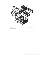
Page 174: ...ane 2 RIO Bus Adapter 7 Model D20 3 PCI X Adapters maximum quantity 7 8 SCSI Cable Bracket 4 Power Supplies 9 PCI Adapter Headstock Bracket 5 I O Backplane 10 Power Supply Bulkhead 5a VPD Module 158 E...

Page 175: ...bsystem chassis are located just below the left SPCN connector and the rack indicator connector 10 Replace the power supply bulkhead by doing the following a Rotate the power supply bulkhead placing t...

Page 176: ...the power cables to the power supplies 22 Reconnect the power source to the system The green LED located on the power supply comes on solid 23 Close and then secure the service access cover with the...

Page 177: ...stem This section lists part numbers for the 7311 Model D10 I O Subsystem This I O subsystem is used in conjunction with a system unit Depending on your configuration the quantities of parts listed ma...

Page 178: ...Screw tray mounting 8 1624743 6 Screw backplane mounting 9 09P5921 1 I O backplane assembly includes SPCN connector card 10 1621829 1 Screw tailstock cover mounting 11 00P4053 1 Dual port RIO bus ada...

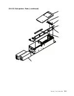
Page 179: ...D10 I O Subsystem Parts continued 1 2 3 4 5 6 7 Chapter 4 Parts Information 163...

Page 180: ...stall Gigabit Ethernet PCI X adapter 44P2661 PCI clip used in PCI adapter cassette to install Ultra SCSI adapter 44P0321 PCI clip used in PCI adapter cassette to install 10 100 Eternet adapter 44P2675...

Page 181: ...87G6235 Up to 9 SPCN cable 2 meter 09P1251 Up to 9 SPCN cable 3 meter 21F9469 Up to 9 SPCN cable 6 meter 21F9358 Up to 9 SPCN cable 15 meter 5 21P5454 Up to 10 RIO 2 cable 1 2 meter 53P2676 Up to 10 R...

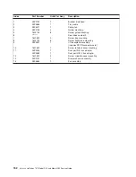
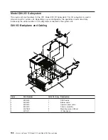
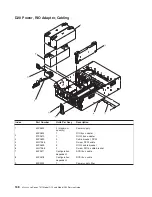
Page 182: ...listed may increase by the actual number of I O subsystems connected to the system unit D20 I O Backplane and Cabling 1 2 3 4 5 6 Index Part Number Units Per Assy Description 1 53P0416 1 DASD cable 2...

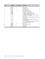
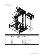
Page 183: ...head 3 44H7366 4 Screw power bulkhead mounting 4 44H7366 3 Screw PCI plate mounting 5 53P0249 1 PCI adapter headstock bracket 6 53P2728 5 PCI dividers 7 53P2729 2 PCI dividers 03K8992 PCI adapter empt...

Page 184: ...2670 1 RIO 2 bus adapter 3 53P2690 3 Cable bracket SCSI 4 44H7366 1 Screw SCSI cable 5 53P0639 5 RIO 2 cable bracket 6 44H7366 2 Screw RIO 2 cable bracket 7 53P0417 Configuration dependent SCSI bus ca...

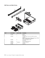
Page 185: ...mber Units Per Assy Description 1 97P3138 2 DASD SCSI Backplane 2 53P0321 4 Screw disk drive backplane mounting 3 53P0330 1 Operator panel 4 53P0275 1 Processor cover 5 44H7366 4 Screw cover mounting...

Page 186: ...planes included Note If the light pipes attached to the cage get broken the entire cage needs to be replaced 4 53P0319 8 Screw DASD cage mounting 5 Disk Drives 6 53P0234 4 Screw filler plate mounting...

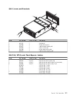
Page 187: ...embly right D20 RIO SPCN and Rack Beacon Cables Index Part Number Units Per Assy Description 1 53P2231 Up to 12 Rack beacon cable junction box 2 53P2237 Up to 12 Rack beacon connector cable 4 pin conn...

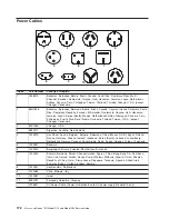
Page 188: ...New Zealand 4 13F9979 Abu Dhabi Austria Belgium Bulgaria Botswana China Macau S A R Egypt Finland France Germany Greece Iceland Indonesia Korea South Lebanon Luxembourg Netherlands Norway Portugal Sa...

Page 189: ...ters and disk drives LEDs are either green or amber Green LEDs indicate one of two things v Electrical power is present v Activity is occuring on a link The system could be sending or receiving inform...

Page 190: ...front of Model D10 On rear of Model D20 Green Standby Off System On Standby Disk Drives DASD Slot Power DASD Backplane External Front Green Power Off Power On N A Activity DASD Backplane External Fron...

Page 191: ...ble Location LED Color OFF ON Blink Power and Packaging LEDs Disk Drive Backplane No LED Port LED Indicators RIOPorts Identify Top of Each External Connector External Back Amber Normal N A Identify Ch...

Page 192: ...e type diag 3 Select Task Selection 4 Select Log Repair Action 5 Select the device that was repaired 6 Press F10 to exit diagnostics If the attention LED remains on after you have completed the repair...

Page 193: ...to applicable regulations IBM offers product return programs in several countries For country specific instructions refer to the following web site http www ibm com ibm environment products prp phtml...

Page 194: ...ek voor informatie over de batterij De batterij moet correct worden gerecycled of weggegooid Mogelijk zijn er in uw regio geen K CA inzamelingspunten Meer informatie over het verwerken van gebruikte b...

Page 195: ...manuale di assistenza per informazioni specifiche sulla batteria La batteria deve essere appropriatamente riciclata o smaltita Il servizio per il riciclaggio potrebbero non essere disponibile nella v...

Page 196: ...mation finns I anv ndar eller servicehandboken Batteriet m ste l mnas till tervinning eller kastas p ett milj s kert s tt Det kanske inte finns n gra tervinningsm jligheter d r du bor N r det g ller o...

Page 197: ...he IBM part number listed on the battery available prior to your call Environmental Design The environmental efforts that have gone into the design of this system signify IBM s commitment to improve t...

Page 198: ...is the upper limit A weighted sound power level LpAm is the mean A weighted sound pressure level at the 1 meter bystander positions 1 B 10 dB 4 All measurements made in conformance with ISO 7779 and...

Page 199: ...typographical errors Changes are periodically made to the information herein these changes will be incorporated in new editions of the publication The manufacturer may make improvements and or changes...

Page 200: ...ibm environment products batteryrecycle shtml or contact your local waste disposal facility In the United States IBM has established a return process for reuse recycling or proper disposal of used IB...

Page 201: ...14 D10 I O subsystem front 10 D10 I O subsystem rear 11 D10 locations continued I O backplane 12 model D10 15 PHB 13 D10 replacement procedure list 42 D20 location code table 32 D20 location codes 31...

Page 202: ...ponent 39 173 component LEDs 173 fault LEDs 173 resetting 176 resetting LEDs 176 location codes 14 31 location codes physical 14 31 locations D10 10 locations D20 19 M MAP rules 40 N noise emissions a...

Page 203: ...on 113 stopping the system 42 removal procedure list D10 42 removal procedure list D20 112 removal procedures 41 adapter PCI D20 130 bezel D20 116 blower cable D20 122 blowers hot swap D20 119 caution...

Page 204: ...rvice position 113 service position D10 43 SPCN cables 5 SPCN cables parts 171 specifications 35 specifications power cables 37 stopping the system 42 subsystem cables 5 subsystem power 4 18 system st...

Page 205: ...s Very Satisfied Satisfied Neutral Dissatisfied Very Dissatisfied Accurate h h h h h Complete h h h h h Easy to find h h h h h Easy to understand h h h h h Well organized h h h h h Applicable to your...

Page 206: ...S 905 6C006 11501 Burnet Road Austin TX 78758 3493 _ _ _ _ _ _ _ _ _ _ _ _ _ _ _ _ _ _ _ _ _ _ _ _ _ _ _ _ _ _ _ _ _ _ _ _ _ _ _ _ _ _ _ _ _ _ _ _ _ _ _ _ _ _ _ _ _ _ _ _ _ _ _ _ _ _ _ _ _ _ _ _ _ _ _...

Page 207: ......
Page 208: ...Printed in USA May 2003 SA38 0627 01...

Reviews: