Handling
Static-Sensitive
Devices
Attention:
Electronic
boards
and
disk
drives
are
sensitive
to
static
electricity
discharge.
These
devices
are
wrapped
in
antistatic
bags
to
prevent
this
damage.
Take
the
following
precautions:
v
If
you
have
an
antistatic
wrist
strap
available,
use
it
while
handling
the
device.
v
Do
not
remove
the
device
from
the
antistatic
bag
until
you
are
ready
to
install
the
device
in
the
system.
v
With
the
device
still
in
its
antistatic
bag,
touch
it
to
a
metal
frame
of
the
system.
v
Grasp
cards
and
boards
by
the
edges.
Hold
drives
by
the
frame.
Avoid
touching
the
solder
joints
or
pins.
v
If
you
need
to
lay
the
device
down
while
it
is
out
of
the
antistatic
bag,
lay
it
on
the
antistatic
bag.
Before
picking
it
up
again,
touch
the
antistatic
bag
and
the
metal
frame
of
the
system
at
the
same
time.
v
Handle
the
devices
carefully
to
prevent
permanent
damage.
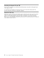
Stopping
and
Starting
the
System
For
procedures
to
power
the
system
on
and
off,
refer
to
the
service
guide
of
the
processor
subsystem
to
which
the
I/O
subsystem
is
attached.
Removal
and
Replacement
Procedures
for
the
Model
D10
I/O
Subsystem
The
following
procedures
cover
the
removal
and
replacement
of
the
Model
D10
I/O
Subsystem
FRUs.
Note:
Before
performing
any
of
the
removal
or
replacement
procedures
in
this
chapter,
read
the
danger
and
caution
notices
on
“Safety
Considerations”
on
page
41.
Model
D10
FRU
Replacement
Procedure
List
Field
Replaceable
Unit
(FRU)
FRU
Procedure
Name
and
Page
Location
Adapters
“PCI
Adapters”
on
page
45
Bezel
“D10
Front
Bezel”
on
page
43
Cover
“D10
Covers”
on
page
44
Blower
“D10
Fan”
on
page
108
I/O
Backplane
“D10
I/O
Backplane
Assembly”
on
page
110
Operating
Position
“D10
Operating
Position”
on
page
43
Power
Supplies
“D10
Power
Supply”
on
page
111
RIO
Bus
Adapter
“D10
RIO
Bus
Adapter
Assembly”
on
page
109
Service
Position
“D10
Service
Position”
on
page
43
Static-Sensitive
Devices
“Handling
Static-Sensitive
Devices”
Stopping
and
Starting
the
System
“Stopping
and
Starting
the
System”
42
Eserver
pSeries
7311
Model
D10
and
Model
D20
Service
Guide
Summary of Contents for eserver pSeries 7311 D10
Page 1: ...pSeries 7311 Model D10 and Model D20 Service Guide SA38 0627 01 ERserver...
Page 2: ......
Page 3: ...pSeries 7311 Model D10 and Model D20 Service Guide SA38 0627 01 ERserver...
Page 8: ...vi Eserver pSeries 7311 Model D10 and Model D20 Service Guide...
Page 12: ...x Eserver pSeries 7311 Model D10 and Model D20 Service Guide...
Page 14: ...xii Eserver pSeries 7311 Model D10 and Model D20 Service Guide...
Page 25: ...1 Processor Subsystem 2 I O Subsystem Chapter 1 Reference Information 9...
Page 89: ...Chapter 3 Removal and Replacement Procedures 73...
Page 99: ...2 1 1 Top of Cassette 2 Handle Chapter 3 Removal and Replacement Procedures 83...
Page 179: ...D10 I O Subsystem Parts continued 1 2 3 4 5 6 7 Chapter 4 Parts Information 163...
Page 207: ......

