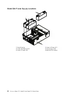
Model
D20
Power
The
Model
D20
is
standard
with
one
power
supply.
If
the
customer
wants
redundant
power
in
their
I/O
subsystem,
an
optional
power
supply
can
be
ordered.
Either
power
supply,
in
a
Model
D20
that
is
configured
with
two
power
supplies,
can
provide
the
necessary
voltages
and
currents,
independent
of
the
other
power
supply.
The
left
and
right
power-supply
output
voltages
are
connected
and
monitored
by
the
power
distribution
board
contained
in
the
I/O
subsystem.
The
left
and
right
power
supplies
are
hot-pluggable
and
may
be
changed
one
at
a
time
while
the
system
is
operational.
Each
power
supply
is
capable
of
converting
available
110/220
V
ac
to
the
proper
internal
voltages
used
by
the
system
components.
The
internal
voltage
range
is
5
volts
system
standby,
3.3
volts,
5
volts,
12
volts
and
-12
volts.
When
operating
correctly,
each
supply
will
share
the
current
load
when
powered
on.
When
in
a
fault
state,
the
operating
power
supply
will
supply
standby
current
to
the
faulted
supply
for
the
DEVROS
module.
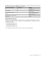
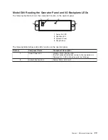
The
following
table
describes
power-related
LED
indicators
that
are
available
on
the
Model
D20.
The
operator
panel
LED
referred
to
in
the
following
table
is
on
the
front
of
the
processor
subsystem
to
which
the
I/O
subsystem
is
attached.
Status
of
LED
Operator
Panel
LED
(processor
subsystem)
Off
Power
Source
not
connected
Blinking
green
LED
System
power
source
connected,
but
power
is
not
turned
on
Blinking
green
LED,
visibly
begins
to
blink
faster
after
the
power-button
has
been
pressed.
System
power
source
connected,
the
power-on
button
has
been
pressed
and
power-on
initiated
Solid
(not
blinking)
green
LED,
(There
is
approximately
a
30-second
transition
period
from
the
time
the
power
on
button
is
pressed
to
the
time
the
power
LED
is
on
solid.)
System
power
source
connected
and
turned
on
Model
D20
Cooling
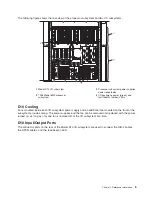
Four
blowers
are
mounted
on
the
top
of
the
I/O
subsystem
to
provide
cooling.
Attention:
The
four
cooling
blowers
mounted
on
top
of
the
Model
D20
are
hot-plug.
The
one
exception
is
when
your
subsystem
has
only
one
power
supply
either
installed
or
functioning,
in
which
case
you
must
shut
down
the
system
and
subsystem.
Failure
to
do
so
will
automatically
shut
down
the
system.
D20
Input/Output
Ports
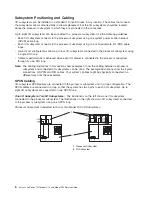
The
connector
ports
on
the
rear
of
the
Model
D20
I/O
subsystem
are
used
to
connect
the
RIO-2
cables,
the
SPCN
cables,
and
the
rack-beacon
LED.
18
Eserver
pSeries
7311
Model
D10
and
Model
D20
Service
Guide
Summary of Contents for eserver pSeries 7311 D10
Page 1: ...pSeries 7311 Model D10 and Model D20 Service Guide SA38 0627 01 ERserver...
Page 2: ......
Page 3: ...pSeries 7311 Model D10 and Model D20 Service Guide SA38 0627 01 ERserver...
Page 8: ...vi Eserver pSeries 7311 Model D10 and Model D20 Service Guide...
Page 12: ...x Eserver pSeries 7311 Model D10 and Model D20 Service Guide...
Page 14: ...xii Eserver pSeries 7311 Model D10 and Model D20 Service Guide...
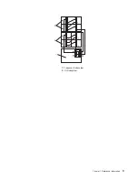
Page 25: ...1 Processor Subsystem 2 I O Subsystem Chapter 1 Reference Information 9...
Page 89: ...Chapter 3 Removal and Replacement Procedures 73...
Page 99: ...2 1 1 Top of Cassette 2 Handle Chapter 3 Removal and Replacement Procedures 83...
Page 179: ...D10 I O Subsystem Parts continued 1 2 3 4 5 6 7 Chapter 4 Parts Information 163...
Page 207: ......

