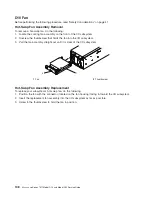
D20
Front
Bezel
Before
performing
the
following
procedure,
read
the
“Safety
Considerations”
on
page
41.
Front
Bezel
Removal
To
remove
the
front
bezel,
do
the
following:
1.
Open
the
front
rack
door.
If
necessary,
place
the
Model
D20
subsystem
into
the
service
position
as
described
in
“D20
Service
Position”
on
page
113.
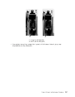
2.
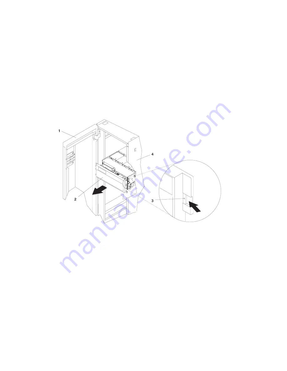
Simultaneously
press
in
both
bezel-release
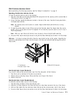
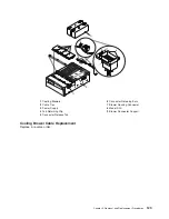
tabs.
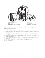
See
the
following
illustration
for
bezel-release
tab
locations.
3.
Pivoting
the
bezel
from
the
bottom,
swing
the
top
of
the
bezel
out.
4.
Pull
the
bottom
of
the
bezel
up,
and
then
away
from
the
subsystem
chassis.
This
action
releases
the
two
tabs
located
on
the
bottom
of
the
bezel.
5.
Put
the
bezel
in
a
safe
place.
1
Rack
Door
3
Bezel-Release
Tab
(Located
on
each
side
of
bezel)
2
Bezel
4
19-Inch
Rack
Front
Bezel
Replacement
To
replace
the
front
bezel,
do
the
following:
1.
Open
the
front
rack
door.
If
necessary,
put
the
Model
D20
subsystem
into
the
service
position
as
described
in
“D20
Service
Position”
on
page
113.
2.
Insert
the
two
tabs
located
on
the
bottom
edge
of
the
bezel
into
their
locking
slots,
located
on
the
chassis.
3.
Pivot
the
front
bezel
up
toward
the
top
of
the
chassis.
4.
Align
the
release
tabs
to
the
matching
slots
located
on
the
front
of
the
subsystem
chassis.
5.
Gently
push
the
tabs
into
the
slots
until
the
bezel
seats
against
the
front
of
the
subsystem.
6.
If
the
subsystem
is
in
the
service
position,
put
the
subsystem
back
into
the
operating
position
as
described
in
“D20
Operating
Position”
on
page
114.
7.
Close
the
rack
door.
116
Eserver
pSeries
7311
Model
D10
and
Model
D20
Service
Guide
Summary of Contents for eserver pSeries 7311 D10
Page 1: ...pSeries 7311 Model D10 and Model D20 Service Guide SA38 0627 01 ERserver...
Page 2: ......
Page 3: ...pSeries 7311 Model D10 and Model D20 Service Guide SA38 0627 01 ERserver...
Page 8: ...vi Eserver pSeries 7311 Model D10 and Model D20 Service Guide...
Page 12: ...x Eserver pSeries 7311 Model D10 and Model D20 Service Guide...
Page 14: ...xii Eserver pSeries 7311 Model D10 and Model D20 Service Guide...
Page 25: ...1 Processor Subsystem 2 I O Subsystem Chapter 1 Reference Information 9...
Page 89: ...Chapter 3 Removal and Replacement Procedures 73...
Page 99: ...2 1 1 Top of Cassette 2 Handle Chapter 3 Removal and Replacement Procedures 83...
Page 179: ...D10 I O Subsystem Parts continued 1 2 3 4 5 6 7 Chapter 4 Parts Information 163...
Page 207: ......

