19.
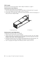
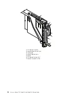
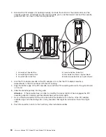
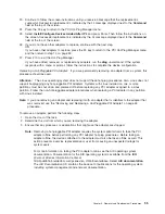
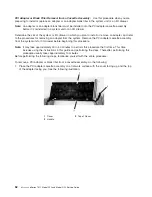
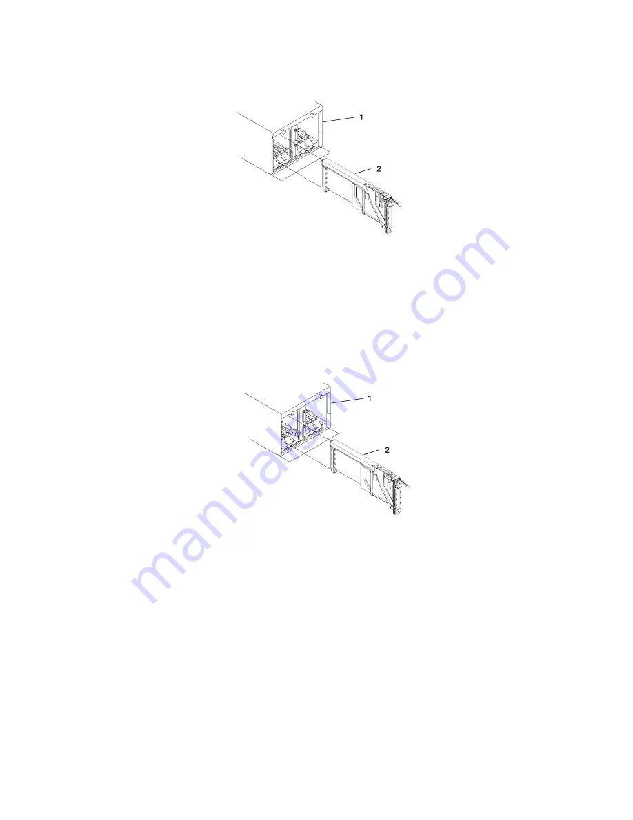
Carefully
pull
the
PCI
adapter
cassette
straight
out
from
the
rear
of
the
subsystem.
Take
care
not
to
pull
EMC
gaskets
from
neighboring
cassettes.
1
I/O
Subsystem
2
PCI
Adapter
Cassette
20.
Install
the
replacement
adapter
in
the
PCI
adapter
cassette,
see
“PCI
Adapter
or
Blank
Filler
Removal
from
a
Cassette
Assembly”
on
page
62.
21.
When
the
adapter
is
installed
in
the
PCI
adapter
cassette,
install
the
adapter
in
the
adapter
slot,
as
follows:
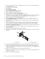
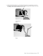
a.
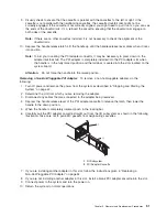
Lower
the
black
handle
completely.
b.
Push
the
locking
bar
until
you
hear
a
clicking
sound.
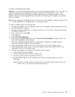
c.
Hold
the
assembly
straight
on
and
level
with
the
slot.
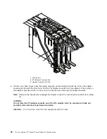
1
I/O
Subsystem
2
PCI
Adapter
Cassette
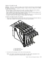
d.
Align
the
bottom
edge
of
the
PCI
cassette
cover
with
the
PCI
adapter
guide
rail
on
the
I/O
backplane.
Note:
If
there
is
a
cassette
to
the
left
of
the
one
that
you
are
installing,
align
the
ridge
on
the
cover
with
the
tick
in
the
notch
of
the
neighboring
cassette.
e.
Slide
the
cassette
partially
into
the
guide.
f.
Ensure
that
the
dovetail
on
the
top
track
aligns
with
its
mating
component(s)
on
both
sides.
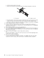
g.
When
the
cassette
is
fully
inserted,
prepare
to
activate
the
handle,
lower
the
locking
bar.
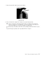
Lift
the
handle
up
completely
until
you
hear
a
click.
The
PCI
adapter
should
be
completely
seated.
Note:
To
enable
proper
insertion
of
the
adapter,
some
minor
forward
or
backward
movement
of
the
PCI
adapter
cassette
might
be
necessary.
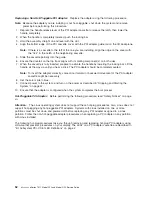
h.
Set
the
color
slide
to
the
orange
color
indicating
that
the
adapter
in
the
cassette
is
hot-pluggable.
22.
Connect
appropriate
cables
and
devices
to
the
adapter.
54
Eserver
pSeries
7311
Model
D10
and
Model
D20
Service
Guide
Summary of Contents for eserver pSeries 7311 D10
Page 1: ...pSeries 7311 Model D10 and Model D20 Service Guide SA38 0627 01 ERserver...
Page 2: ......
Page 3: ...pSeries 7311 Model D10 and Model D20 Service Guide SA38 0627 01 ERserver...
Page 8: ...vi Eserver pSeries 7311 Model D10 and Model D20 Service Guide...
Page 12: ...x Eserver pSeries 7311 Model D10 and Model D20 Service Guide...
Page 14: ...xii Eserver pSeries 7311 Model D10 and Model D20 Service Guide...
Page 25: ...1 Processor Subsystem 2 I O Subsystem Chapter 1 Reference Information 9...
Page 89: ...Chapter 3 Removal and Replacement Procedures 73...
Page 99: ...2 1 1 Top of Cassette 2 Handle Chapter 3 Removal and Replacement Procedures 83...
Page 179: ...D10 I O Subsystem Parts continued 1 2 3 4 5 6 7 Chapter 4 Parts Information 163...
Page 207: ......

