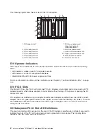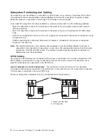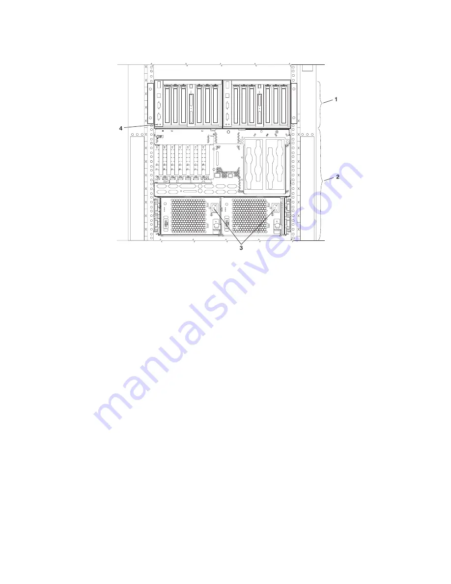
The
following
figure
shows
the
rear
view
of
the
processor
subsystem
and
two
I/O
subsystems.
1
Model
D10
I/O
subsystem
3
Processor
subsystem
power
supplies,
power
receptacles
2
7038
Model
6M2
processor
subsystem
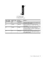
4
I/O
backplane
power
(green)
and
fault/identify
(amber)
LEDs
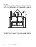
D10
Cooling
Fans
mounted
inside
each
I/O
subsystem
power
supply
and
an
additional
fan
mounted
on
the
front
of
the
subsystem
provide
cooling.
The
power
supplies
and
the
fan
can
be
removed
and
replaced
with
the
power
turned
on,
as
long
as
only
one
fan
is
removed
from
the
I/O
subsystem
at
a
time.
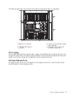
D10
Input/Output
Ports
The
connector
ports
on
the
rear
of
the
Model
D10
I/O
subsystem
are
used
to
connect
the
RIO-2
cables,
the
SPCN
cables,
and
the
rack-beacon
LED.
Chapter
1.
Reference
Information
5
Summary of Contents for eserver pSeries 7311 D10
Page 1: ...pSeries 7311 Model D10 and Model D20 Service Guide SA38 0627 01 ERserver...
Page 2: ......
Page 3: ...pSeries 7311 Model D10 and Model D20 Service Guide SA38 0627 01 ERserver...
Page 8: ...vi Eserver pSeries 7311 Model D10 and Model D20 Service Guide...
Page 12: ...x Eserver pSeries 7311 Model D10 and Model D20 Service Guide...
Page 14: ...xii Eserver pSeries 7311 Model D10 and Model D20 Service Guide...
Page 25: ...1 Processor Subsystem 2 I O Subsystem Chapter 1 Reference Information 9...
Page 89: ...Chapter 3 Removal and Replacement Procedures 73...
Page 99: ...2 1 1 Top of Cassette 2 Handle Chapter 3 Removal and Replacement Procedures 83...
Page 179: ...D10 I O Subsystem Parts continued 1 2 3 4 5 6 7 Chapter 4 Parts Information 163...
Page 207: ......

