6.
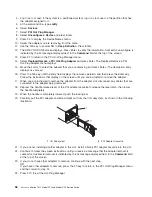
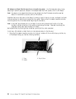
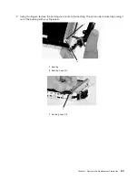
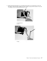
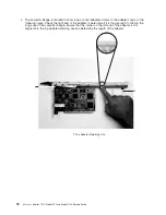
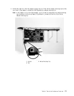
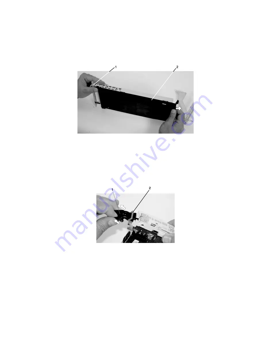
Turn
over
the
cassette
so
that
the
cover
is
facing
up,
as
shown
in
the
following
illustration.
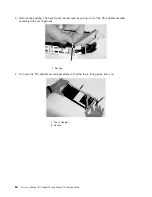
Remove
the
cover
from
the
cassette
as
follows:
a.
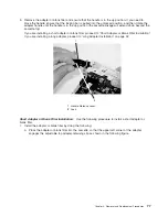
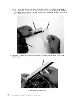
Slide
the
cover
until
it
releases
from
the
cassette
assembly.
Attention:
The
cover
might
be
tight
and
difficult
to
slide.
If
you
grasp
the
left
end
(handle
end)
of
the
cassette
and
the
right
end
of
the
cover,
you
can
use
enough
force
to
pull
the
cover
off
the
PCI
adapter
cassette
assembly.
1
Left
End
of
the
Cassette
2
Cassette
Cover
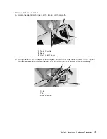
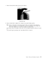
b.
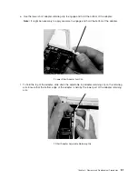
Lift
the
cover
off
the
assembly,
and
set
it
aside.
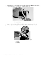
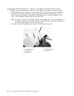
c.
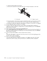
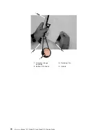
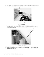
Depress
the
handle
release
lever
to
unlock
the
locking
bar.
The
locking
bar
is
located
on
the
handle,
ensure
that
the
handle
is
pulled
into
the
unlocked
position.
Raise
the
handle
on
the
cassette
linkage
assembly
until
it
locks
into
the
up
position
(the
blank
filler
or
adapter
moves
downward).
1
Handle
Release
Lever
2
Locking
Bar
68
Eserver
pSeries
7311
Model
D10
and
Model
D20
Service
Guide
Summary of Contents for eserver pSeries 7311 D10
Page 1: ...pSeries 7311 Model D10 and Model D20 Service Guide SA38 0627 01 ERserver...
Page 2: ......
Page 3: ...pSeries 7311 Model D10 and Model D20 Service Guide SA38 0627 01 ERserver...
Page 8: ...vi Eserver pSeries 7311 Model D10 and Model D20 Service Guide...
Page 12: ...x Eserver pSeries 7311 Model D10 and Model D20 Service Guide...
Page 14: ...xii Eserver pSeries 7311 Model D10 and Model D20 Service Guide...
Page 25: ...1 Processor Subsystem 2 I O Subsystem Chapter 1 Reference Information 9...
Page 89: ...Chapter 3 Removal and Replacement Procedures 73...
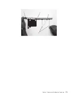
Page 99: ...2 1 1 Top of Cassette 2 Handle Chapter 3 Removal and Replacement Procedures 83...
Page 179: ...D10 I O Subsystem Parts continued 1 2 3 4 5 6 7 Chapter 4 Parts Information 163...
Page 207: ......


