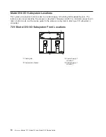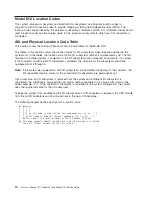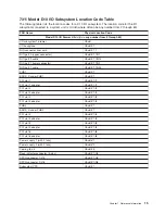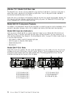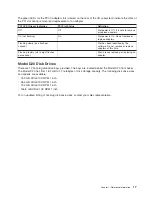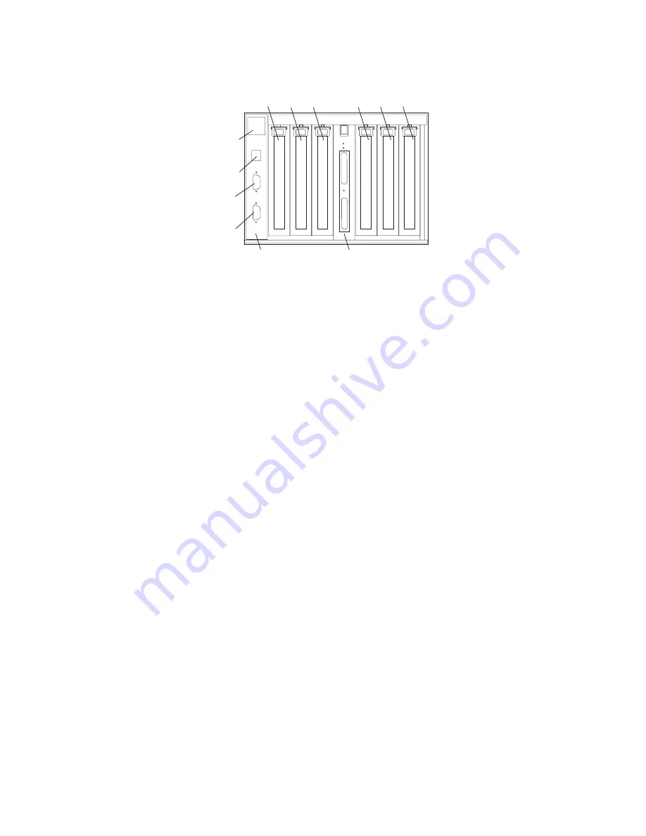
7311
Model
D10
I/O
Subsystem
Rear
Locations
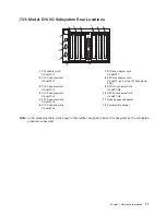
1
2
3
4
5
6
1
2
3
4
5
6
7
8
9
11
10
12
1
PCI
adapter
slot
1
U0.
dd
-P1-I1
7
RIO
bus
adapter
card
U0.
dd
-P1.1
2
PCI-X
adapter
slot
2
U0.
dd
-P1-I2
8
SPCN
connector
card
U0.
dd
-P1
(part
of
the
I/O
backplane
FRU)
3
PCI-X
adapter
slot
3
U0.
dd
-P1-I3
9
SPCN
Connector
2/J16
U0.
dd
P1/Q5
4
PCI-X
adapter
slot
4
U0.
dd
-P1-I4
10
SPCN
Connector
1/J15
U0.
dd
P1/Q4
5
PCI-X
adapter
slot
5
U0.
dd
-P1-I5
11
Rack
beacon
connector
6
PCI-X
adapter
slot
6
U0.
dd
-P1-I6
12
Power
cord
channel
Note:
In
the
preceding
table,
dd
is
equal
to
the
number
assigned
to
each
I/O
subsystem
by
the
connected
processor
subsystem.
Chapter
1.
Reference
Information
11
Summary of Contents for eserver pSeries 7311 D10
Page 1: ...pSeries 7311 Model D10 and Model D20 Service Guide SA38 0627 01 ERserver...
Page 2: ......
Page 3: ...pSeries 7311 Model D10 and Model D20 Service Guide SA38 0627 01 ERserver...
Page 8: ...vi Eserver pSeries 7311 Model D10 and Model D20 Service Guide...
Page 12: ...x Eserver pSeries 7311 Model D10 and Model D20 Service Guide...
Page 14: ...xii Eserver pSeries 7311 Model D10 and Model D20 Service Guide...
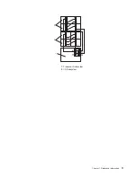
Page 25: ...1 Processor Subsystem 2 I O Subsystem Chapter 1 Reference Information 9...
Page 89: ...Chapter 3 Removal and Replacement Procedures 73...
Page 99: ...2 1 1 Top of Cassette 2 Handle Chapter 3 Removal and Replacement Procedures 83...
Page 179: ...D10 I O Subsystem Parts continued 1 2 3 4 5 6 7 Chapter 4 Parts Information 163...
Page 207: ......

