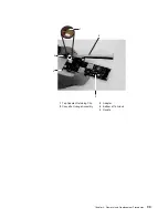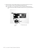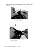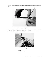
3)
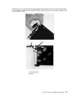
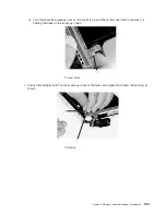
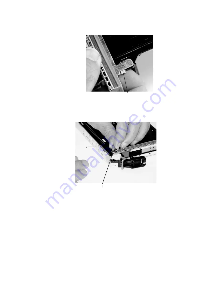
Turn
the
cassette
assembly
over
so
the
cover
is
up
and
check
the
cover
latch
to
ensure
it
is
holding
the
bezel
to
the
cover
as
shown.
1
1
Cover
Latch
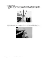
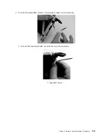
l.
Position
the
adapter
with
the
cover
side
up.
Ensure
the
holes
are
aligned
and
insert
the
bushing
as
shown.
1
Bushing
Chapter
3.
Removal
and
Replacement
Procedures
103
Summary of Contents for eserver pSeries 7311 D10
Page 1: ...pSeries 7311 Model D10 and Model D20 Service Guide SA38 0627 01 ERserver...
Page 2: ......
Page 3: ...pSeries 7311 Model D10 and Model D20 Service Guide SA38 0627 01 ERserver...
Page 8: ...vi Eserver pSeries 7311 Model D10 and Model D20 Service Guide...
Page 12: ...x Eserver pSeries 7311 Model D10 and Model D20 Service Guide...
Page 14: ...xii Eserver pSeries 7311 Model D10 and Model D20 Service Guide...
Page 25: ...1 Processor Subsystem 2 I O Subsystem Chapter 1 Reference Information 9...
Page 89: ...Chapter 3 Removal and Replacement Procedures 73...
Page 99: ...2 1 1 Top of Cassette 2 Handle Chapter 3 Removal and Replacement Procedures 83...
Page 179: ...D10 I O Subsystem Parts continued 1 2 3 4 5 6 7 Chapter 4 Parts Information 163...
Page 207: ......

