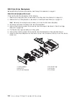
Disk
Drive
Backplane
Replacement
To
replace
the
disk
drive
backplane,
do
the
following:
1.
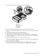
Reconnect
the
power/signal
cable
to
the
connector
located
on
the
top
edge
of
the
disk
drive
backplane.
2.
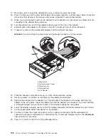
Grasp
a
bottom
edge
of
one
of
the
connectors
located
on
the
disk
drive
backplane,
and
insert
the
backplane
into
the
disk
drive
bay.
3.
Using
the
3
supplied
retaining
screws,
secure
the
disk
drive
backplane
to
the
subsystem
chassis.
4.
Carefully
insert
the
disk
drive
cage
assembly
into
the
system.
5.
Align
and
then
secure
the
disk
drive
cage
to
the
subsystem
chassis
with
the
7
previously
removed
retaining
screws.
6.
Before
handling
any
card,
board,
or
memory
DIMM,
be
sure
to
use
your
electrostatic
discharge
strap
to
minimize
static-electric
discharge.
Refer
to
“Handling
Static-Sensitive
Devices”
on
page
42.
7.
Replace
all
hot-plug
disk
drives
as
described
in
“Hot-Plug
Disk
Drive
Replacement”
on
page
145.
8.
Reconnect
the
power
source
to
the
system.
9.
Replace
the
front
bezel
as
described
in
“Front
Bezel
Replacement”
on
page
116.
10.
Power
on
the
system
as
described
in
“Stopping
and
Starting
the
System”
on
page
42.
11.
Close
and
then
secure
the
service
access
cover
with
the
three
thumbscrews
located
on
its
back
edge.
12.
Return
the
subsystem
into
the
operating
position
as
described
in
“D20
Operating
Position”
on
page
114.
13.
Close
the
rack
front
door.
Chapter
3.
Removal
and
Replacement
Procedures
149
Summary of Contents for eserver pSeries 7311 D10
Page 1: ...pSeries 7311 Model D10 and Model D20 Service Guide SA38 0627 01 ERserver...
Page 2: ......
Page 3: ...pSeries 7311 Model D10 and Model D20 Service Guide SA38 0627 01 ERserver...
Page 8: ...vi Eserver pSeries 7311 Model D10 and Model D20 Service Guide...
Page 12: ...x Eserver pSeries 7311 Model D10 and Model D20 Service Guide...
Page 14: ...xii Eserver pSeries 7311 Model D10 and Model D20 Service Guide...
Page 25: ...1 Processor Subsystem 2 I O Subsystem Chapter 1 Reference Information 9...
Page 89: ...Chapter 3 Removal and Replacement Procedures 73...
Page 99: ...2 1 1 Top of Cassette 2 Handle Chapter 3 Removal and Replacement Procedures 83...
Page 179: ...D10 I O Subsystem Parts continued 1 2 3 4 5 6 7 Chapter 4 Parts Information 163...
Page 207: ......

